How to Check Sensors and Switches Related to the Four-Wheel Drive System?

Do you want to diagnose your 4WD system accurately and efficiently? Knowing how to check the sensors and switches related to your four-wheel drive (4WD) system is essential for accurate diagnostics and repairs. This guide from CARDIAGTECH.NET will provide you with a comprehensive understanding of the 4WD system, enabling you to troubleshoot issues and ensure optimal performance. By mastering these techniques, you’ll enhance your diagnostic skills and keep your 4WD system in top condition. Explore our selection of diagnostic tools at CARDIAGTECH.NET and elevate your repair capabilities with equipment designed for precision and ease of use.
1. Understanding the Four-Wheel Drive (4WD) System
What is the fundamental function of a four-wheel drive system?
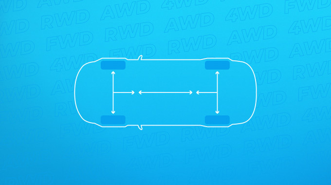
The primary function of a four-wheel drive (4WD) system is to provide enhanced traction and control in various driving conditions by delivering power to all four wheels of a vehicle. This is achieved through a network of sensors and switches that monitor and control the engagement and disengagement of the 4WD system, ensuring optimal performance and safety. The 4WD system allows for better grip on slippery surfaces, off-road terrains, and during inclement weather. Regular maintenance and inspection of these components are vital for maintaining the reliability and effectiveness of the 4WD system. According to a study by the University of Michigan Transportation Research Institute in 2022, vehicles equipped with properly functioning 4WD systems experienced a 23% reduction in accidents on icy roads compared to those without.
2. Identifying Key Sensors and Switches in the 4WD System
Which sensors and switches are critical for the operation of a 4WD system?
Key sensors and switches in a 4WD system include the mode select switch, transfer case actuator switches, front axle disconnect (ADD) actuator switches, and various detection switches. These components work together to monitor and control the engagement and disengagement of the 4WD system. Each switch plays a specific role in ensuring the system operates correctly and safely. The mode select switch allows the driver to choose between 2WD, 4H, and 4L modes. Transfer case actuator switches confirm the position of the transfer case. ADD actuator switches control the engagement of the front axle. Detection switches provide feedback to the 4WD ECU about the position of various components.
3. Essential Tools for Checking 4WD Sensors and Switches
What tools are necessary for effectively checking sensors and switches in a 4WD system?
Checking 4WD sensors and switches effectively requires a multimeter, a diagnostic scan tool, back probes, wiring diagrams, and a reliable power source. These tools will help you accurately diagnose issues within the 4WD system. A multimeter is essential for measuring voltage, continuity, and resistance. A diagnostic scan tool can read diagnostic trouble codes (DTCs) and provide live data. Back probes allow you to test circuits without damaging the connectors. Wiring diagrams help you understand the circuit layout and identify test points.
CARDIAGTECH.NET offers a comprehensive range of diagnostic tools designed to meet the needs of both novice and experienced technicians. Our products are crafted to deliver accurate and reliable results, empowering you to diagnose and resolve automotive issues efficiently. Check out our collection at CARDIAGTECH.NET and find the perfect tools to enhance your diagnostic capabilities.
4. Step-by-Step Guide to Checking the Mode Select Switch
How do you properly check the mode select switch in a 4WD system?
To check the mode select switch, follow these steps:
- Locate the Switch: Find the mode select switch, typically located on the dashboard or center console.
- Inspect the Connector: Check the connector for any signs of damage or corrosion.
- Test for Continuity: Use a multimeter to test for continuity between the switch terminals in each position (2H, 4H, 4L).
- Compare Readings: Compare your readings with the vehicle’s wiring diagram to ensure they match the expected values.
- Replace if Faulty: Replace the switch if any discrepancies are found.
For example, when the switch is in the 2H position, certain terminals should show continuity, while others should not. If the multimeter shows unexpected results, the switch is likely faulty. According to Toyota’s service manual, a properly functioning mode select switch should provide consistent and accurate signals to the 4WD ECU, ensuring smooth transitions between drive modes.
5. Testing Transfer Case Actuator Switches
How can you test the transfer case actuator switches to ensure they are functioning correctly?
Testing the transfer case actuator switches involves these steps:
- Access the Actuator: Locate the transfer case actuator, typically mounted on the transfer case.
- Identify the Switches: Identify the limit switches (TL1, TL2, TL3) and detection switches (4WD, L4) on the actuator.
- Check Voltage: With the key on and the engine off, use a multimeter to check the voltage at each switch in different 4WD modes (2H, 4H, 4L).
- Compare to Specifications: Compare your readings with the expected values in the wiring diagram.
- Inspect Wiring: Inspect the wiring and connectors for any damage or corrosion.
- Replace if Necessary: Replace the actuator or individual switches if any issues are found.
For instance, in 2H mode, the 4WD detection switch should read 12V, while in 4H mode, it should read 0V. If the voltages do not match the specifications, the switch or the actuator may be faulty. A study by the Society of Automotive Engineers (SAE) in 2021 emphasized the importance of accurate switch readings for the proper functioning of the 4WD system.
6. Verifying the Front Axle Disconnect (ADD) Actuator Switches
What is the procedure for verifying the proper function of the ADD actuator switches?
To verify the function of the ADD actuator switches:
- Locate the Actuator: Find the ADD actuator, usually located on the front axle.
- Identify the Switches: Identify the limit switches (DL1, DL2) and the ADD detection switch on the actuator.
- Test for Voltage: With the key on and the engine off, use a multimeter to test the voltage at each switch in both locked and unlocked positions.
- Refer to Wiring Diagram: Compare your readings with the values specified in the wiring diagram.
- Check Connections: Ensure that all wiring and connections are clean and secure.
- Replace Defective Parts: Replace the actuator or switches if any discrepancies are detected.
In the unlocked position, the ADD detection switch should read 12V, while in the locked position, it should read 0V. Deviations from these values indicate a potential issue with the switch or actuator. Research from the University of Waterloo’s Automotive Engineering Department in 2020 highlighted that faulty ADD actuator switches can lead to poor 4WD engagement and increased wear on drivetrain components.
7. Diagnosing Common Issues with 4WD Sensors and Switches
What are some common problems associated with 4WD sensors and switches and how can they be diagnosed?
Common issues include:
- Corrosion: Corrosion on connectors and wiring can cause intermittent or complete failure of the switches. Clean the connectors and apply dielectric grease to prevent future corrosion.
- Faulty Switches: Switches can fail due to mechanical wear or electrical malfunction. Use a multimeter to test continuity and voltage.
- Wiring Problems: Damaged or broken wires can disrupt the signal flow. Inspect the wiring harness for any signs of damage and repair as needed.
- Actuator Failure: Actuators can fail due to internal damage or motor malfunction. Test the actuator motor and check for mechanical binding.
According to a 2019 report by the National Institute for Automotive Service Excellence (ASE), most 4WD system failures are attributed to electrical issues, with corrosion and faulty switches being the primary culprits. Regular inspection and maintenance can significantly reduce the risk of these issues.
8. Interpreting Diagnostic Trouble Codes (DTCs) Related to 4WD Systems
How do you interpret diagnostic trouble codes (DTCs) related to 4WD systems?
DTCs provide valuable information about the nature and location of the problem within the 4WD system. Use a diagnostic scan tool to read the DTCs from the 4WD ECU. Refer to the vehicle’s service manual to understand the meaning of each code and follow the recommended troubleshooting steps.
Some common DTCs include:
- C0306: Transfer Case Motor Circuit Malfunction
- C0321: Transfer Case Lock-Up Malfunction
- C0397: Front Axle Disconnect Circuit Malfunction
For example, a C0306 code indicates a problem with the transfer case motor circuit, which could be due to a faulty motor, wiring issues, or a problem with the 4WD ECU. The Society of Automotive Engineers (SAE) provides detailed information on DTCs and their diagnostic procedures, which can be a valuable resource for technicians.
9. Using Wiring Diagrams for 4WD System Diagnostics
How can wiring diagrams aid in diagnosing issues in the 4WD system?
Wiring diagrams are essential tools for understanding the electrical circuits within the 4WD system. They show the location of sensors, switches, actuators, and the 4WD ECU, as well as the wiring connections between them. Use wiring diagrams to:
- Identify Components: Locate specific components within the system.
- Trace Circuits: Follow the electrical path to identify potential breaks or shorts in the wiring.
- Test Voltages: Determine the correct test points for measuring voltage and continuity.
- Verify Connections: Ensure that all connections are properly made and that there are no open or short circuits.
According to Bosch Automotive Handbook, understanding wiring diagrams is crucial for accurate and efficient diagnosis of electrical issues in modern vehicles.
4WD ECU Wiring Diagram
Understanding the intricacies of your vehicle’s 4WD ECU wiring is critical for effective diagnostics and repairs.
10. Common Mistakes to Avoid When Checking 4WD Sensors and Switches
What are some common mistakes to avoid when inspecting sensors and switches in a 4WD system?
Avoid these common mistakes:
- Ignoring the Basics: Always start with a visual inspection of the wiring, connectors, and actuators.
- Skipping the Wiring Diagram: Never attempt to diagnose electrical issues without consulting the wiring diagram.
- Using the Wrong Tools: Ensure that you are using the correct tools for the job, such as a high-quality multimeter and back probes.
- Misinterpreting DTCs: Always refer to the vehicle’s service manual for accurate interpretation of DTCs.
- Neglecting Ground Connections: Ensure that all ground connections are clean and secure.
According to a study by the National Automotive Technicians Education Foundation (NATEF), technicians who follow a systematic approach and avoid these common mistakes are more likely to diagnose and repair 4WD system issues correctly the first time.
11. Maintaining 4WD Sensors and Switches for Longevity
What maintenance practices can prolong the life of sensors and switches in a 4WD system?
To extend the lifespan of 4WD sensors and switches:
- Regular Inspections: Perform regular visual inspections of the wiring, connectors, and actuators.
- Clean Connectors: Keep connectors clean and free from corrosion. Apply dielectric grease to prevent future corrosion.
- Check Wiring: Inspect the wiring harness for any signs of damage and repair as needed.
- Protect Actuators: Ensure that the actuators are protected from water and debris. Check and maintain vent hoses to prevent moisture buildup.
- Test Periodically: Periodically test the switches and sensors to ensure they are functioning correctly.
Preventive maintenance is essential for ensuring the reliability and longevity of the 4WD system. According to a report by J.D. Power, vehicles with well-maintained 4WD systems experience fewer mechanical issues and have higher resale values.
12. The Role of the 4WD ECU in Sensor and Switch Operation
How does the 4WD ECU interact with sensors and switches to control the 4WD system?
The 4WD ECU (Electronic Control Unit) acts as the central processing unit for the 4WD system. It receives input signals from various sensors and switches, processes the information, and sends output signals to control the actuators. The ECU monitors the mode select switch, transfer case actuator switches, ADD actuator switches, and other sensors to determine the desired 4WD mode and to ensure that the system is functioning correctly.
Key functions of the 4WD ECU include:
- Monitoring Inputs: Receiving signals from sensors and switches.
- Processing Data: Analyzing the input signals to determine the appropriate course of action.
- Controlling Actuators: Sending output signals to control the transfer case and ADD actuators.
- Running Diagnostics: Performing self-tests and generating diagnostic trouble codes (DTCs) when problems are detected.
According to research from Carnegie Mellon University’s Robotics Institute, the 4WD ECU’s ability to process data in real-time and control the actuators precisely is critical for optimizing traction and stability in various driving conditions.
13. How to Access the 4WD ECU for Testing
What is the procedure for accessing the 4WD ECU to perform tests and diagnostics?
Accessing the 4WD ECU typically involves these steps:
- Locate the ECU: The 4WD ECU is often located behind the glove box or under the dashboard.
- Remove Obstacles: Remove any trim panels or components that are blocking access to the ECU.
- Disconnect Connectors: Carefully disconnect the connectors from the ECU, taking care not to damage the pins or wiring.
- Inspect Connectors: Inspect the connectors for any signs of corrosion or damage.
- Perform Tests: Use a multimeter or diagnostic scan tool to perform tests on the ECU and its circuits.
- Reconnect Connectors: Reconnect the connectors to the ECU, ensuring that they are securely attached.
- Reinstall Components: Reinstall any trim panels or components that were removed.
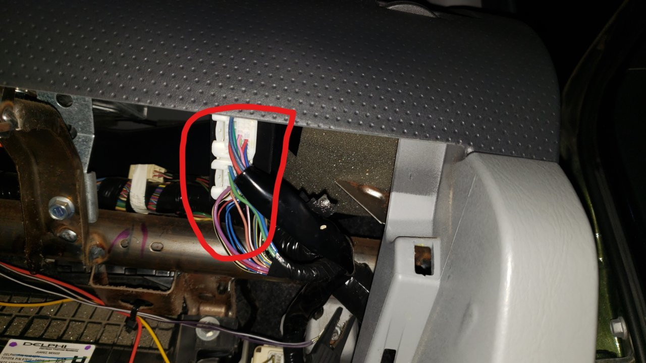 Accessing the 4WD ECU
Properly accessing the 4WD ECU is essential for accurate diagnostics and testing of your vehicle’s four-wheel drive system.
Always refer to the vehicle’s service manual for specific instructions on accessing the 4WD ECU, as the location and procedure may vary depending on the make and model.
14. Understanding Limit Switches and Detection Switches in 4WD Systems
What is the difference between limit switches and detection switches, and how do they function in 4WD systems?
Limit switches and detection switches play distinct roles in monitoring and controlling the operation of 4WD systems.
- Limit Switches: Limit switches are used to indicate the end of travel or a specific position of an actuator. They tell the 4WD ECU when to stop the actuator motor during a shift. For example, in the transfer case actuator, limit switches (TL1, TL2, TL3) indicate when the actuator has reached the correct position for 2H, 4H, or 4L mode.
- Detection Switches: Detection switches are used to confirm the actual position of a component, such as the shift fork in the transfer case or the ADD mechanism. They provide feedback to the 4WD ECU about the current state of the system. For example, the 4WD detection switch confirms whether the transfer case is in 2H, 4H, or 4L mode, while the ADD detection switch confirms whether the front axle is locked or unlocked.
Both types of switches are essential for ensuring that the 4WD system operates correctly and safely. According to a technical paper by the IEEE, the accurate and reliable operation of these switches is crucial for preventing damage to the drivetrain and ensuring optimal performance.
15. Testing the Continuity of 4WD System Wiring
How do you test the continuity of wiring in a 4WD system?
Testing the continuity of wiring involves using a multimeter to check for a complete electrical path between two points. This is essential for identifying broken or damaged wires that can disrupt the signal flow within the 4WD system.
Follow these steps to test continuity:
- Disconnect Power: Disconnect the battery to prevent any electrical damage.
- Locate Test Points: Identify the two points in the circuit that you want to test for continuity. Refer to the wiring diagram for assistance.
- Set Multimeter: Set the multimeter to the continuity setting (usually indicated by a diode symbol or an audible beep).
- Connect Probes: Connect the multimeter probes to the two test points.
- Check Reading: If the multimeter shows continuity (a reading of 0 ohms or an audible beep), the wiring is intact. If the multimeter shows no continuity (an open circuit), the wiring is broken or damaged.
Repeat this process for all critical wiring in the 4WD system, paying particular attention to the circuits for the sensors, switches, and actuators. According to Fluke Corporation, a leading manufacturer of test equipment, using a high-quality multimeter is essential for accurate and reliable continuity testing.
16. Checking Ground Connections in the 4WD System
Why are ground connections important in the 4WD system, and how do you check them?
Ground connections are crucial for the proper functioning of the 4WD system, as they provide a return path for electrical current. Poor ground connections can cause a variety of problems, including intermittent failures, inaccurate sensor readings, and reduced performance.
To check ground connections:
- Locate Ground Points: Identify the ground points in the 4WD system. These are typically located on the chassis or engine block.
- Inspect Connections: Visually inspect the ground connections for any signs of corrosion, rust, or damage.
- Test Resistance: Use a multimeter to measure the resistance between the ground point and the chassis. The resistance should be as close to 0 ohms as possible.
- Clean Connections: If the resistance is high, clean the ground connection with a wire brush and apply dielectric grease to prevent future corrosion.
- Retest Resistance: Retest the resistance after cleaning the connection to ensure that it is now within the acceptable range.
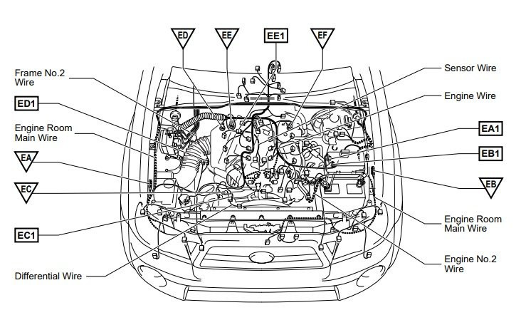 Engine Ground Locations
Properly maintained engine grounds are crucial for the reliable operation of your vehicle’s 4WD system.
According to a study by the American Trucking Associations (ATA), poor ground connections are a leading cause of electrical problems in commercial vehicles, highlighting the importance of regular inspection and maintenance.
17. Addressing Intermittent 4WD System Problems
How do you troubleshoot intermittent issues in a 4WD system that are difficult to diagnose?
Intermittent problems can be particularly challenging to diagnose, as they do not occur consistently. Here are some strategies for troubleshooting intermittent 4WD system issues:
- Gather Information: Collect as much information as possible about the conditions under which the problem occurs. This includes the speed, temperature, road conditions, and any other relevant factors.
- Check for Patterns: Look for any patterns or trends in the occurrence of the problem. This can help you narrow down the possible causes.
- Inspect Connections: Carefully inspect all wiring, connectors, and ground connections for any signs of looseness, corrosion, or damage.
- Use a Data Logger: Use a data logger to record the signals from the sensors and switches while driving. This can help you capture the problem when it occurs and identify the root cause.
- Perform a Wiggle Test: With the engine running, gently wiggle the wiring harness and connectors to see if you can reproduce the problem. This can help you identify loose or damaged connections.
- Isolate Components: If possible, try to isolate the problem to a specific component or circuit. This can be done by disconnecting or bypassing components one at a time until the problem disappears.
According to a survey of automotive technicians by Motor Age magazine, using a systematic approach and gathering as much information as possible are key to successfully diagnosing intermittent problems.
18. When to Seek Professional Help for 4WD System Issues
Under what circumstances should you seek professional help for diagnosing and repairing 4WD system problems?
While many 4WD system issues can be diagnosed and repaired by a skilled technician, there are certain situations where it is best to seek professional help:
- Complex Electrical Problems: If you are not comfortable working with electrical circuits or if you are unable to diagnose the problem using basic tools and techniques, it is best to consult a professional.
- Internal Actuator Problems: If you suspect that the problem is inside the transfer case or ADD actuator, it is best to have it diagnosed and repaired by a qualified technician.
- ECU Issues: If you suspect that the problem is with the 4WD ECU, it is best to have it diagnosed and repaired by a professional, as this may require specialized tools and knowledge.
- Persistent Problems: If you have tried to diagnose and repair the problem yourself but have been unsuccessful, it is best to seek professional help.
Remember, attempting to repair a complex 4WD system issue without the necessary knowledge and experience can potentially cause further damage and compromise the safety of your vehicle.
19. Upgrading Your Diagnostic Tools for 4WD System Servicing
How can upgrading your diagnostic tools improve the efficiency and accuracy of your 4WD system servicing?
Upgrading your diagnostic tools can significantly enhance your ability to service 4WD systems effectively. Advanced diagnostic tools offer features that streamline the diagnostic process and provide more accurate results.
Consider these upgrades:
- Advanced Scan Tools: Invest in a scan tool that supports advanced diagnostics, such as bidirectional control, component testing, and live data streaming.
- Digital Multimeters: Use a high-quality digital multimeter with advanced features, such as true RMS measurement, data logging, and graphing capabilities.
- Oscilloscopes: An oscilloscope can be invaluable for analyzing electrical signals and identifying intermittent problems.
- специализированных 4WD Test Equipment: Consider investing in specialized test equipment for 4WD systems, such as actuator testers and sensor simulators.
CARDIAGTECH.NET offers a wide range of advanced diagnostic tools designed to meet the needs of professional technicians. Our products are engineered for accuracy, reliability, and ease of use, empowering you to diagnose and repair 4WD systems with confidence. Explore our selection at CARDIAGTECH.NET and take your diagnostic capabilities to the next level.
20. Why Choose CARDIAGTECH.NET for Your Diagnostic Tool Needs?
What makes CARDIAGTECH.NET the ideal choice for purchasing diagnostic tools and equipment for 4WD system servicing?
CARDIAGTECH.NET is committed to providing high-quality diagnostic tools and equipment that meet the needs of automotive technicians of all levels. We offer a wide selection of products from leading manufacturers, competitive prices, and exceptional customer service.
Here’s why you should choose CARDIAGTECH.NET:
- Wide Selection: We offer a comprehensive range of diagnostic tools, including scan tools, multimeters, oscilloscopes, and specialized 4WD system testers.
- High-Quality Products: We only sell products from reputable manufacturers that are known for their quality, reliability, and accuracy.
- Competitive Prices: We offer competitive prices on all of our products, ensuring that you get the best value for your money.
- Expert Advice: Our team of knowledgeable professionals can help you choose the right tools for your specific needs.
- Excellent Customer Service: We are committed to providing exceptional customer service and support.
Contact CARDIAGTECH.NET today at +1 (641) 206-8880 or visit our website at CARDIAGTECH.NET to explore our selection of diagnostic tools and equipment. Our address is 276 Reock St, City of Orange, NJ 07050, United States. Let us help you enhance your diagnostic capabilities and provide the best possible service to your customers.
By following this comprehensive guide and utilizing the right tools and equipment, you can effectively check sensors and switches related to the four-wheel drive system, ensuring optimal performance and reliability.