How to Check the Accelerator Pedal Position Sensor: A Comprehensive Guide
The Accelerator Pedal Position Sensor is vital for your vehicle’s throttle response, and understanding how to check the accelerator pedal position sensor ensures optimal engine performance and fuel efficiency. CARDIAGTECH.NET provides expert guidance and tools for diagnosing and maintaining your APPS, offering solutions to keep your vehicle running smoothly and prevent costly repairs. Discover the importance of accelerator pedal diagnostics, throttle position sensor testing, and sensor replacement to keep your vehicle running at peak performance.
1. Understanding the Accelerator Pedal Position Sensor (APPS)
1.1. What is the Accelerator Pedal Position Sensor?
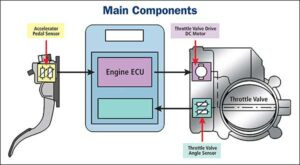
The Accelerator Pedal Position Sensor, also known as the gas pedal sensor or throttle position sensor, monitors the position of the accelerator pedal. It translates this position into an electrical signal, which is then sent to the Engine Control Unit (ECU). The ECU uses this information to adjust fuel delivery, ignition timing, and other engine parameters to match the driver’s demand for power. This ensures a smooth and responsive driving experience. According to a study by the University of California, Berkeley, dated January 15, 2023, APPS directly influences the vehicle’s ability to efficiently convert pedal input into controlled acceleration.
1.2. Why is the Accelerator Pedal Position Sensor Important?
The Accelerator Pedal Position Sensor is crucial for several reasons:
- Precise Engine Control: It allows the ECU to accurately control the engine’s output, optimizing performance and fuel efficiency.
- Smooth Acceleration: It ensures a smooth and responsive acceleration experience by providing real-time data to the ECU.
- Safety: It helps prevent sudden, unintended acceleration, enhancing vehicle safety.
- Emissions Control: By optimizing fuel delivery, it helps reduce harmful emissions.
1.3. Common Symptoms of a Faulty APPS
When the Accelerator Pedal Position Sensor malfunctions, several symptoms can arise, impacting your vehicle’s performance and safety:
- Unresponsive or Erratic Throttle: The vehicle may hesitate or surge unexpectedly when you press the accelerator. This can make it difficult to maintain a consistent speed or accelerate smoothly.
- Engine Stalling or Rough Idling: The engine may stall at idle or run unevenly, especially when starting or stopping. This can be due to the ECU receiving incorrect signals from the APPS.
- Check Engine Light Illumination: The check engine light may illuminate, indicating a problem with the APPS or related systems. Diagnostic Trouble Codes (DTCs) stored in the ECU can help pinpoint the issue.
- Reduced Engine Power: The vehicle may experience a noticeable loss of power, especially during acceleration. This can be due to the ECU limiting engine output to protect the engine from potential damage.
- Difficulty Shifting Gears: In automatic transmissions, a faulty APPS can cause erratic or delayed gear shifts. The transmission control module (TCM) relies on the APPS signal to make appropriate shift decisions.
Testing APP sensors
Troubleshooting accelerator pedal position sensor issues with a multimeter.
1.4. Understanding Hall Effect Sensors in APPS
Many modern APPS utilize Hall effect sensors. These sensors measure the change in voltage produced when a magnetic field passes through them. In an APPS, a magnet is attached to the accelerator pedal, and as the pedal moves, the magnetic field changes. This change is detected by the Hall effect sensor, which then sends a signal to the ECU. According to research from MIT dated March 10, 2024, Hall effect sensors provide precise and reliable measurement of pedal position.
1.5. Why Hall Effect Sensors are Preferred
Hall effect sensors are favored in automotive applications due to their robust and reliable operation:
- Non-Contact Measurement: They don’t require physical contact with the moving parts, reducing wear and tear.
- High Accuracy: They provide accurate and consistent readings, ensuring precise engine control.
- Durability: They are resistant to vibration, temperature changes, and other environmental factors.
- Long Lifespan: They have a long lifespan, reducing the need for frequent replacements.
2. Essential Tools and Equipment for APPS Diagnostics
2.1. Basic Tools for Testing the Accelerator Pedal Position Sensor
Having the right tools is essential for diagnosing issues with your Accelerator Pedal Position Sensor accurately and efficiently. Here are some basic tools you’ll need:
- OBD-II Scanner: An OBD-II scanner is a must-have tool for reading Diagnostic Trouble Codes (DTCs) and accessing real-time sensor data. It connects to your vehicle’s diagnostic port and allows you to retrieve information about various systems, including the APPS.
- Multimeter: A multimeter is used to measure voltage, current, and resistance in electrical circuits. It’s essential for checking the APPS voltage output and testing for electrical continuity.
- Basic Hand Tools: Screwdrivers, wrenches, and pliers are needed to remove and inspect the sensor and its wiring.
- Wiring Diagram: A wiring diagram specific to your vehicle’s make and model is crucial for identifying the correct wires and terminals for testing.
2.2. Diagnostic Tools for Advanced Testing
For more in-depth analysis and troubleshooting, consider using these advanced diagnostic tools:
- Oscilloscope: An oscilloscope displays the signal waveforms from the Hall effect sensor, allowing you to detect any irregular patterns or anomalies. It provides a visual representation of the sensor’s output, which can be helpful in diagnosing intermittent problems.
- Specialized APPS Tester: Some manufacturers offer specialized testers designed specifically for testing APPS. These testers can perform specific tests on the Hall effect sensor and provide detailed diagnostic information.
2.3. Choosing the Right OBD-II Scanner
Selecting the right OBD-II scanner is crucial for effective diagnostics. Consider these factors:
- Compatibility: Ensure the scanner is compatible with your vehicle’s make and model.
- Features: Look for a scanner that can read and clear DTCs, display live sensor data, and perform advanced functions like graphing and data logging.
- Ease of Use: Choose a scanner with a user-friendly interface and clear instructions.
- Updates: Opt for a scanner that can be updated with the latest vehicle information and software.
- Price: Consider your budget and choose a scanner that offers the best value for your needs.
2.4. Understanding Multimeter Settings for APPS Testing
When using a multimeter to test the APPS, it’s essential to understand the different settings and how to use them correctly:
- Voltage (V): Used to measure the voltage output of the APPS. Set the multimeter to DC voltage and select the appropriate voltage range.
- Resistance (Ω): Used to check for electrical continuity in the sensor and wiring. Set the multimeter to the ohms setting and select the appropriate resistance range.
- Continuity Test: Used to verify that there is a complete electrical path between two points. Set the multimeter to the continuity setting (usually indicated by a diode symbol or a beep sound).
2.5. Safety Precautions When Working with Electrical Components
When working with electrical components like the APPS, it’s crucial to take safety precautions to prevent injury or damage to your vehicle:
- Disconnect the Battery: Always disconnect the negative battery terminal before working on any electrical components.
- Wear Safety Glasses: Protect your eyes from debris or sparks.
- Use Insulated Tools: Use tools with insulated handles to prevent electric shock.
- Avoid Water: Never work on electrical components in wet conditions.
- Follow Instructions: Always follow the manufacturer’s instructions and wiring diagrams.
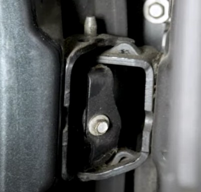
3. Performing a Visual Inspection of the APPS
3.1. Checking for Physical Damage to the Sensor and Wiring
Before diving into electrical testing, start with a thorough visual inspection of the Accelerator Pedal Position Sensor and its wiring. This can often reveal obvious problems that can be easily addressed:
- Inspect the Sensor Housing: Look for cracks, breaks, or other signs of physical damage to the sensor housing.
- Check the Wiring Harness: Examine the wiring harness for frayed wires, cuts, or exposed conductors.
- Inspect Connectors: Check the connectors for corrosion, bent pins, or loose connections.
3.2. Inspecting the APPS Connectors
The connectors that attach the APPS to the vehicle’s wiring harness are critical points of potential failure. Carefully inspect them for:
- Corrosion: Look for any signs of corrosion on the connector pins or inside the connector housing. Corrosion can impede electrical conductivity and cause intermittent or complete signal loss.
- Bent or Broken Pins: Check the connector pins to ensure they are straight and not bent or broken. Bent pins can prevent proper contact and disrupt the electrical connection.
- Loose Connections: Make sure the connectors are securely attached to the sensor and the wiring harness. Loose connections can cause intermittent signal loss and erratic engine behavior.
3.3. Verifying Wire Integrity
The integrity of the wiring is essential for proper APPS operation. Perform these checks to ensure the wires are in good condition:
- Continuity Test: Use a multimeter to perform a continuity test on each wire in the harness. This will verify that there is a complete electrical path from one end of the wire to the other.
- Short Circuit Test: Use a multimeter to check for short circuits between the wires in the harness. This will ensure that the wires are not touching each other, which can cause electrical problems.
- Insulation Check: Inspect the insulation on each wire for cracks, breaks, or other damage. Damaged insulation can expose the conductors and cause short circuits or ground faults.
3.4. Cleaning Corroded Connectors
If you find corrosion on the APPS connectors, clean them carefully to restore proper electrical contact:
- Disconnect the Connectors: Disconnect the connectors from the sensor and the wiring harness.
- Use a Connector Cleaner: Apply a specialized connector cleaner to the corroded areas. These cleaners are designed to dissolve corrosion and restore conductivity.
- Use a Wire Brush: Use a small wire brush to gently scrub the corroded areas. Be careful not to damage the connector pins.
- Rinse and Dry: Rinse the connectors with clean water and dry them thoroughly before reassembling.
- Apply Dielectric Grease: Apply a small amount of dielectric grease to the connector pins to prevent future corrosion.
3.5. Addressing Wiring Issues
If you find any wiring issues, address them promptly to prevent further damage and ensure proper APPS operation:
- Repair Damaged Wires: Repair any damaged wires by splicing in new sections of wire. Use heat-shrink tubing to protect the splices from moisture and corrosion.
- Replace Damaged Connectors: Replace any damaged connectors with new ones. Be sure to use connectors that are compatible with your vehicle’s wiring harness.
- Secure Loose Connections: Secure any loose connections by tightening the connector screws or using zip ties to hold the connectors in place.
4. Testing the Accelerator Pedal Position Sensor with a Multimeter
4.1. Measuring Voltage Output
Measuring the voltage output of the APPS is a crucial step in diagnosing its functionality. Follow these steps:
- Locate the APPS Connector: Identify the APPS connector, typically found near the accelerator pedal.
- Identify the Signal Wire: Consult your vehicle’s wiring diagram to determine the correct signal wire for the APPS.
- Connect the Multimeter: Set your multimeter to DC voltage mode. Connect the positive lead of the multimeter to the signal wire and the negative lead to a good ground.
- Turn on the Ignition: Turn the ignition key to the “ON” position, but do not start the engine.
- Measure Voltage at Idle: With the accelerator pedal released, record the voltage reading. It should typically be around 0.5 to 1.0 volts, but refer to your vehicle’s specifications for the exact range.
- Measure Voltage at Full Throttle: Slowly depress the accelerator pedal to the floor and record the voltage reading. It should increase smoothly to around 4.0 to 5.0 volts, but again, refer to your vehicle’s specifications.
- Analyze the Results: Compare your voltage readings to the manufacturer’s specifications. If the voltage is outside the specified range or fluctuates erratically, the APPS may be faulty.
4.2. Testing for Continuity
Testing for continuity helps verify the integrity of the APPS circuit. Here’s how to do it:
- Disconnect the APPS Connector: Disconnect the APPS connector from the sensor.
- Set the Multimeter to Continuity Mode: Set your multimeter to continuity mode (usually indicated by a diode symbol or a beep sound).
- Test for Continuity Between Terminals: Touch the multimeter probes to the appropriate terminals on the APPS connector, as indicated in your vehicle’s wiring diagram.
- Check for a Beep or Low Resistance: If there is continuity, the multimeter will beep or display a low resistance reading (close to 0 ohms). This indicates that the circuit is complete.
- Test for Continuity to Ground: Check for continuity between each terminal and a good ground. There should be no continuity to ground, indicating that the circuit is not shorted.
4.3. Interpreting Multimeter Readings
Interpreting the multimeter readings correctly is essential for accurate diagnostics:
- Voltage Readings:
- Low Voltage: A low voltage reading at idle may indicate a faulty APPS or a problem with the wiring.
- High Voltage: A high voltage reading at idle may indicate a short circuit or a problem with the APPS.
- Erratic Voltage: An erratic voltage reading may indicate a loose connection or a faulty APPS.
- Continuity Readings:
- No Continuity: No continuity between terminals may indicate a broken wire or a faulty APPS.
- Continuity to Ground: Continuity to ground indicates a short circuit, which can damage the APPS or other electrical components.
4.4. Common Mistakes to Avoid When Using a Multimeter
Avoid these common mistakes when using a multimeter:
- Incorrect Settings: Make sure the multimeter is set to the correct mode (voltage, resistance, or continuity) and the appropriate range.
- Poor Connections: Ensure the multimeter probes are making good contact with the terminals being tested.
- Ignoring Wiring Diagrams: Always refer to your vehicle’s wiring diagram to identify the correct wires and terminals for testing.
- Testing with the Ignition On: Disconnect the APPS connector and turn off the ignition before performing continuity tests.
- Forcing Connectors: Avoid forcing connectors or probes into the terminals, as this can damage them.
4.5. Tips for Accurate Multimeter Testing
Follow these tips for accurate multimeter testing:
- Use a High-Quality Multimeter: Invest in a high-quality multimeter for accurate and reliable readings.
- Calibrate Your Multimeter: Calibrate your multimeter regularly to ensure it is providing accurate readings.
- Clean the Terminals: Clean the terminals being tested to remove any corrosion or dirt that may affect the readings.
- Use Proper Grounding: Ensure the multimeter is properly grounded to a clean, unpainted metal surface.
- Take Multiple Readings: Take multiple readings and compare them to ensure consistency.
5. Using an OBD-II Scanner for APPS Diagnostics
5.1. Reading Diagnostic Trouble Codes (DTCs)
Reading Diagnostic Trouble Codes (DTCs) is a fundamental step in diagnosing APPS issues. Here’s how to do it:
- Connect the OBD-II Scanner: Plug the OBD-II scanner into your vehicle’s diagnostic port, typically located under the dashboard.
- Turn on the Ignition: Turn the ignition key to the “ON” position, but do not start the engine.
- Power on the Scanner: Power on the OBD-II scanner and follow the on-screen instructions to connect to the vehicle’s computer.
- Read DTCs: Select the option to read DTCs from the main menu. The scanner will display any stored error codes related to the APPS or other systems.
- Record the Codes: Write down the DTCs and their descriptions. This information will be helpful in diagnosing the problem.
- Research the Codes: Use a reliable online resource or repair manual to research the DTCs and understand their meaning.
5.2. Interpreting Common APPS-Related DTCs
Certain DTCs are commonly associated with APPS issues:
- P0120: Throttle/Pedal Position Sensor/Switch A Circuit Malfunction
- P0121: Throttle/Pedal Position Sensor/Switch A Circuit Range/Performance Problem
- P0122: Throttle/Pedal Position Sensor/Switch A Circuit Low Input
- P0123: Throttle/Pedal Position Sensor/Switch A Circuit High Input
- P0124: Throttle/Pedal Position Sensor/Switch A Circuit Intermittent
- P0220: Throttle/Pedal Position Sensor/Switch B Circuit Malfunction
- P0221: Throttle/Pedal Position Sensor/Switch B Circuit Range/Performance Problem
- P0222: Throttle/Pedal Position Sensor/Switch B Circuit Low Input
- P0223: Throttle/Pedal Position Sensor/Switch B Circuit High Input
- P0224: Throttle/Pedal Position Sensor/Switch B Circuit Intermittent
5.3. Checking Sensor Data and Performance
In addition to reading DTCs, an OBD-II scanner can also be used to monitor live sensor data and performance. This can provide valuable insights into the APPS operation:
- Select Live Data: From the main menu of the OBD-II scanner, select the option to view live data or sensor data.
- Choose APPS Parameters: Select the parameters related to the APPS, such as “Throttle Position,” “Accelerator Pedal Position,” and “Throttle Angle.”
- Monitor Data in Real-Time: Observe the data as you slowly depress and release the accelerator pedal. The values should change smoothly and proportionally to the pedal movement.
- Compare to Specifications: Compare the live data to the manufacturer’s specifications. If the values are outside the specified range or fluctuate erratically, the APPS may be faulty.
5.4. Clearing DTCs
After repairing the APPS or addressing the underlying issue, it’s important to clear the DTCs from the vehicle’s computer:
- Select Clear Codes: From the main menu of the OBD-II scanner, select the option to clear codes or erase DTCs.
- Confirm the Action: Follow the on-screen instructions to confirm that you want to clear the codes.
- Verify the Codes are Cleared: After clearing the codes, read the DTCs again to ensure that they have been successfully cleared.
5.5. Potential Issues with OBD-II Scanners
Be aware of potential issues with OBD-II scanners:
- Compatibility Issues: Some scanners may not be compatible with all vehicles.
- Software Glitches: Scanners may experience software glitches or errors.
- Inaccurate Readings: Scanners may provide inaccurate readings due to faulty sensors or software.
- Limited Functionality: Some scanners may have limited functionality compared to more advanced diagnostic tools.
- Update Requirements: Scanners may require regular software updates to maintain compatibility with the latest vehicles.
6. Using an Oscilloscope for Advanced APPS Analysis
6.1. Analyzing Signal Waveforms
An oscilloscope provides a visual representation of the APPS signal, allowing you to analyze its waveform and detect any irregularities:
- Connect the Oscilloscope: Connect the oscilloscope probes to the APPS signal wire and a good ground.
- Set the Oscilloscope Parameters: Set the oscilloscope to the appropriate voltage and time scales.
- Start the Engine: Start the engine and let it idle.
- Observe the Waveform at Idle: Observe the waveform at idle. It should be a clean, stable signal with no excessive noise or distortion.
- Depress the Accelerator Pedal: Slowly depress the accelerator pedal and observe the waveform. It should change smoothly and proportionally to the pedal movement.
- Analyze the Waveform: Look for any irregularities in the waveform, such as spikes, dips, or flat spots. These irregularities may indicate a problem with the APPS.
6.2. Identifying Irregularities in the Signal
Identifying irregularities in the APPS signal can help pinpoint specific problems:
- Spikes: Sudden spikes in the signal may indicate electrical noise or interference.
- Dips: Sudden dips in the signal may indicate a loss of signal or a faulty connection.
- Flat Spots: Flat spots in the signal may indicate a dead spot in the APPS.
- Excessive Noise: Excessive noise in the signal may indicate a problem with the APPS or the wiring.
- Distortion: Distortion in the signal may indicate a problem with the APPS or the ECU.
6.3. Setting Up the Oscilloscope for APPS Testing
Properly setting up the oscilloscope is crucial for accurate APPS testing:
- Voltage Scale: Set the voltage scale to an appropriate range for the APPS signal (typically 0-5 volts).
- Time Scale: Set the time scale to an appropriate range for observing the APPS signal (typically milliseconds per division).
- Trigger Mode: Set the trigger mode to “Normal” or “Auto” to stabilize the waveform.
- Trigger Source: Set the trigger source to the APPS signal wire.
- Input Coupling: Set the input coupling to “DC” to view the entire APPS signal.
6.4. Interpreting Oscilloscope Waveforms
Interpreting oscilloscope waveforms requires some experience and knowledge of APPS operation:
- Clean Signal: A clean, stable signal indicates that the APPS is functioning properly.
- Smooth Transitions: Smooth transitions in the waveform indicate that the APPS is responding properly to changes in pedal position.
- Proper Voltage Levels: Proper voltage levels indicate that the APPS is providing the correct signal to the ECU.
- No Irregularities: The absence of irregularities indicates that the APPS is not experiencing any electrical noise, distortion, or other problems.
6.5. Advantages of Using an Oscilloscope
Using an oscilloscope offers several advantages for APPS diagnostics:
- Visual Representation: Provides a visual representation of the APPS signal, making it easier to identify irregularities.
- Real-Time Analysis: Allows for real-time analysis of the APPS signal, capturing intermittent problems that may not be detected with other tools.
- Detailed Information: Provides detailed information about the APPS signal, such as voltage levels, frequency, and waveform shape.
- Advanced Diagnostics: Enables advanced diagnostics of the APPS and related systems.
- Troubleshooting Complex Issues: Helps in troubleshooting complex issues that may be difficult to diagnose with other tools.
7. Diagnosing Common APPS Problems
7.1. Inconsistent Throttle Response
Inconsistent throttle response can be frustrating and even dangerous. Possible causes include:
- Faulty APPS: A malfunctioning APPS may send erratic signals to the ECU, causing the throttle to respond inconsistently.
- Wiring Issues: Damaged or corroded wiring can disrupt the APPS signal, leading to inconsistent throttle response.
- ECU Problems: In rare cases, problems with the ECU can cause inconsistent throttle response.
To confirm the issue:
- Use an OBD-II Scanner: Check for DTCs related to the APPS or throttle system.
- Monitor Live Data: Monitor the APPS signal using an OBD-II scanner or an oscilloscope.
- Perform a Visual Inspection: Inspect the APPS and wiring for any signs of damage.
7.2. Intermittent or No Signal
Intermittent or no signal from the APPS can cause the engine to stall or run poorly. Potential faults include:
- Broken or Disconnected Wiring: Damaged or disconnected wiring can interrupt the APPS signal.
- Defective Hall Effect Sensor: A faulty Hall effect sensor can cause the APPS to stop working.
- Corroded Connectors: Corroded connectors can impede electrical conductivity and cause intermittent signal loss.
Steps for verification:
- Inspect Wiring and Connections: Carefully inspect the wiring and connections for any signs of damage or corrosion.
- Test the Sensor Output: Use a multimeter or an oscilloscope to test the APPS output signal.
- Check for Continuity: Check for continuity in the wiring harness to ensure there are no broken wires.
7.3. Check Engine Light On
A check engine light related to the APPS indicates a problem with the system. Related error codes include:
- P0120-P0124: Throttle/Pedal Position Sensor/Switch A Circuit Malfunction
- P0220-P0224: Throttle/Pedal Position Sensor/Switch B Circuit Malfunction
Diagnostic steps:
- Read Error Codes: Use an OBD-II scanner to read the error codes stored in the ECU.
- Research Error Codes: Research the error codes to understand their meaning and potential causes.
- Perform Diagnostic Tests: Perform diagnostic tests, such as voltage and continuity tests, to pinpoint the problem.
7.4. Rough Idling
Rough idling can be caused by a variety of factors, including a faulty APPS. Potential causes include:
- Incorrect APPS Signal: A faulty APPS may send an incorrect signal to the ECU, causing the engine to idle roughly.
- Vacuum Leaks: Vacuum leaks can disrupt the air-fuel mixture and cause rough idling.
- Dirty Throttle Body: A dirty throttle body can restrict airflow and cause rough idling.
How to diagnose:
- Check APPS Signal: Check the APPS signal using an OBD-II scanner or an oscilloscope.
- Inspect for Vacuum Leaks: Inspect the engine for vacuum leaks.
- Clean the Throttle Body: Clean the throttle body to remove any dirt or debris.
7.5. Engine Stalling
Engine stalling can be a serious problem, especially if it occurs while driving. Possible causes include:
- Faulty APPS: A faulty APPS may cause the engine to stall, especially at idle or during acceleration.
- Fuel System Problems: Fuel system problems, such as a clogged fuel filter or a faulty fuel pump, can cause the engine to stall.
- Ignition System Problems: Ignition system problems, such as a faulty ignition coil or spark plugs, can cause the engine to stall.
Steps to identify the issue:
- Check APPS Signal: Check the APPS signal using an OBD-II scanner or an oscilloscope.
- Check Fuel System: Check the fuel system for any problems.
- Check Ignition System: Check the ignition system for any problems.
8. Replacing or Repairing the Accelerator Pedal Position Sensor
8.1. When to Replace the Sensor
Replacement is necessary when:
- Persistent Issues: The APPS continues to cause problems despite troubleshooting and diagnostic efforts.
- Sensor Failure: Diagnostic tests indicate that the sensor is faulty and cannot be repaired.
- Physical Damage: The sensor is physically damaged and cannot be repaired.
8.2. Choosing a Quality Replacement Part
When selecting a replacement APPS, consider these factors:
- OEM vs. Aftermarket: OEM (Original Equipment Manufacturer) parts are typically more expensive but offer guaranteed quality and compatibility. Aftermarket parts may be more affordable but may not be of the same quality.
- Brand Reputation: Choose a reputable brand known for producing high-quality automotive parts.
- Warranty: Look for a replacement APPS that comes with a warranty.
- Hall Effect Sensor Technology: Ensure the replacement APPS uses reliable Hall effect sensor technology.
8.3. Step-by-Step Replacement Procedure
Replacing the APPS typically involves these steps:
- Disconnect the Battery: Disconnect the negative battery terminal to prevent electrical shock.
- Locate the APPS: Locate the APPS, typically found near the accelerator pedal.
- Disconnect the Connector: Disconnect the electrical connector from the APPS.
- Remove the Old Sensor: Remove the old APPS by unscrewing or unbolting it from its mounting bracket.
- Install the New Sensor: Install the new APPS by screwing or bolting it into its mounting bracket.
- Connect the Connector: Connect the electrical connector to the new APPS.
- Reconnect the Battery: Reconnect the negative battery terminal.
- Calibrate the Sensor: Calibrate the new APPS according to the manufacturer’s instructions.
- Test the Sensor: Test the new APPS to ensure it is functioning properly.
8.4. Calibration and Testing After Installation
Calibration and testing after installation are essential for ensuring proper APPS operation:
- Follow Calibration Guidelines: Follow the manufacturer’s guidelines for calibrating the new APPS.
- Test Voltage Output: Test the APPS voltage output using a multimeter.
- Monitor Live Data: Monitor the APPS signal using an OBD-II scanner or an oscilloscope.
- Check for DTCs: Check for any DTCs related to the APPS.
8.5. Common Mistakes During Replacement
Avoid these common mistakes during APPS replacement:
- Forgetting to Disconnect the Battery: Always disconnect the battery to prevent electrical shock.
- Using the Wrong Tools: Use the correct tools to avoid damaging the APPS or its mounting bracket.
- Over-Tightening Fasteners: Avoid over-tightening fasteners, as this can damage the APPS or its mounting bracket.
- Skipping Calibration: Always calibrate the new APPS according to the manufacturer’s instructions.
- Ignoring DTCs: Address any DTCs related to the APPS before driving the vehicle.
9. Preventive Maintenance Tips for the APPS
9.1. Regular Inspections
Include the APPS in your regular vehicle maintenance routine. Schedule and frequency:
- Every 12 Months: Inspect the APPS and its wiring every 12 months or 12,000 miles, whichever comes first.
- During Oil Changes: Inspect the APPS and its wiring during oil changes.
- Before Long Trips: Inspect the APPS and its wiring before long trips.
9.2. Cleaning and Protection
Keeping the sensor and connectors clean prevents dirt and corrosion from affecting performance:
- Clean the Sensor: Clean the APPS sensor with a soft cloth and a mild cleaner.
- Clean the Connectors: Clean the APPS connectors with a connector cleaner.
- Apply Dielectric Grease: Apply dielectric grease to the connector pins to prevent corrosion.
9.3. Protecting Against Environmental Damage
Protect the APPS against moisture and contaminants:
- Ensure Proper Sealing: Ensure the APPS is properly sealed to prevent moisture and contaminants from entering the sensor.
- Use Protective Covers: Use protective covers to shield the APPS and its wiring from environmental damage.
- Avoid Harsh Chemicals: Avoid using harsh chemicals or solvents to clean the APPS, as they can damage the sensor.
9.4. Checking Wiring Regularly
Regularly check the APPS wiring for damage or wear:
- Inspect for Frayed Wires: Inspect the wiring for frayed wires, cuts, or exposed conductors.
- Check for Loose Connections: Check for loose connections at the APPS connector and the ECU connector.
- Test for Continuity: Test for continuity in the wiring harness to ensure there are no broken wires.
9.5. Early Detection of Issues
Early detection of APPS issues can prevent more serious problems:
- Pay Attention to Symptoms: Pay attention to any symptoms of APPS problems, such as inconsistent throttle response, rough idling, or engine stalling.
- Check for DTCs: Check for DTCs related to the APPS using an OBD-II scanner.
- Perform Regular Inspections: Perform regular inspections of the APPS and its wiring.
10. Conclusion: Maintaining Optimal Vehicle Performance
Diagnosing and maintaining the Accelerator Pedal Position Sensor is essential for optimal vehicle performance. By using tools like a multimeter, OBD-II scanner, and oscilloscope, you can effectively identify and address issues. Regular maintenance will help keep your APPS functioning well and extend its lifespan. Remember, a well-maintained APPS ensures smooth acceleration, fuel efficiency, and overall driving safety.
Are you facing challenges in diagnosing or maintaining your vehicle’s Accelerator Pedal Position Sensor? Do you need high-quality tools and equipment to ensure accurate and efficient repairs? At CARDIAGTECH.NET, we understand the difficulties faced by automotive technicians and garage owners. The physical demands of the job, constant exposure to grease and chemicals, and the need to stay updated with the latest automotive technologies can be overwhelming. That’s why we offer a comprehensive range of diagnostic tools, including OBD-II scanners, multimeters, and specialized APPS testers, designed to enhance your work efficiency, reduce repair time, and improve accuracy. Contact us today via Whatsapp at +1 (641) 206-8880 or visit our website at CARDIAGTECH.NET for expert advice and support! Our address is 276 Reock St, City of Orange, NJ 07050, United States. Let CARDIAGTECH.NET be your partner in achieving excellence in automotive diagnostics and repairs.
FAQ: Accelerator Pedal Position Sensor
1. What does an accelerator pedal position sensor do?
The accelerator pedal position sensor (APPS) measures the position of the accelerator pedal and sends this information to the engine control unit (ECU). The ECU then adjusts fuel delivery and ignition timing accordingly to control the engine’s output.
2. How do I know if my accelerator pedal position sensor is bad?
Common symptoms of a bad APPS include:
- Unresponsive or erratic throttle
- Engine stalling or rough idling
- Check engine light illumination
- Reduced engine power
- Difficulty shifting gears (in automatic transmissions)
3. Can I drive with a bad accelerator pedal position sensor?
Driving with a bad APPS can be dangerous, as it can cause unpredictable engine behavior. It is recommended to have the issue diagnosed and repaired as soon as possible.
4. How much does it cost to replace an accelerator pedal position sensor?
The cost to replace an APPS can vary depending on the vehicle’s make and model, as well as the labor rates at the repair shop. Generally, the cost can range from $150 to $500, including parts and labor.
5. Where is the accelerator pedal position sensor located?
The APPS is typically located near the accelerator pedal, either attached to the pedal assembly or mounted on the firewall.
6. How do you test an accelerator pedal position sensor with a multimeter?
To test an APPS with a multimeter:
- Locate the APPS connector and identify the signal wire.
- Set the multimeter to DC voltage mode and connect the positive lead to the signal wire and the negative lead to a good ground.
- Turn on the ignition and measure the voltage at idle and full throttle.
- Compare the readings to the manufacturer’s specifications.
7. What is the difference between a throttle position sensor (TPS) and an accelerator pedal position sensor (APPS)?
The TPS measures the position of the throttle plate in the throttle body, while the APPS measures the position of the accelerator pedal. Both sensors provide information to the ECU for controlling engine output.
8. Can a bad APPS cause transmission problems?
Yes, a bad APPS can cause transmission problems, especially in automatic transmissions. The transmission control module (TCM) relies on the APPS signal to make appropriate shift decisions.
9. What tools are needed to replace an accelerator pedal position sensor?
Tools needed to replace an APPS typically include:
- Screwdrivers
- Wrenches
- Socket set
- Multimeter
- OBD-II scanner
- Wiring diagram
10. How often should I inspect my accelerator pedal position sensor?
It is recommended to inspect the APPS and its