How to Check the Air Flow Control Valves (Mode Door Actuator)?
Checking the air flow control valves, also known as mode door actuators, is essential for maintaining your vehicle’s climate control system and CARDIAGTECH.NET offers the tools you need. This in-depth guide provides comprehensive insights and methods to diagnose and resolve issues related to these critical components, ensuring optimal performance and passenger comfort. Learn about actuator diagnostics, climate control systems, and repair solutions.
1. Understanding Air Flow Control Valves (Mode Door Actuators)
Air flow control valves, or mode door actuators, are electro-mechanical devices in your vehicle’s HVAC (Heating, Ventilation, and Air Conditioning) system. These actuators control the direction of airflow by opening, closing, or modulating various doors and dampers inside the HVAC unit. By directing air through different vents, they allow you to select where the air comes out—defroster, face vents, floor vents—and help regulate temperature.
1.1. Importance of Properly Functioning Actuators
Properly functioning actuators are crucial for several reasons:
- Comfort: They ensure that the air is directed to the desired location, providing comfort for the driver and passengers.
- Defogging and Defrosting: They allow air to be directed to the windshield for defogging and defrosting, essential for safe driving in inclement weather.
- Temperature Control: By regulating airflow, they help maintain the desired temperature inside the vehicle.
- System Efficiency: Efficient operation of the HVAC system ensures that the vehicle does not waste energy, which can impact fuel economy.
1.2. Common Symptoms of a Failing Actuator
Recognizing the symptoms of a failing actuator can help you address the issue promptly. Common signs include:
- Inconsistent Airflow: Air only comes out of certain vents regardless of the selected mode.
- No Airflow: No air comes out of any vents.
- Clicking or Thumping Noises: A repetitive clicking or thumping sound coming from under the dashboard.
- Incorrect Temperature: Air temperature does not match the setting (e.g., cold air when set to heat).
- Delayed Response: A noticeable delay when switching between modes.
- Airflow Changes on Its Own: The direction of airflow changes without any input.
Addressing these symptoms early can prevent further damage and maintain the functionality of your HVAC system. CARDIAGTECH.NET provides the tools and knowledge to diagnose and resolve these issues efficiently.
2. Tools and Equipment Needed for Inspection
Before you begin checking your air flow control valves, ensure you have the necessary tools and equipment to facilitate a thorough inspection. Having the right tools not only makes the job easier but also ensures accuracy and safety.
2.1. Essential Tools
-
Scan Tool: A diagnostic scan tool is indispensable for reading trouble codes related to the HVAC system. Modern vehicles store diagnostic trouble codes (DTCs) that can pinpoint the exact location and nature of the problem. Scan tools range from basic code readers to advanced models that can perform bidirectional control tests.
-
Multimeter: A multimeter is essential for testing electrical circuits and components. It allows you to measure voltage, current, and resistance, which are crucial for diagnosing electrical issues with the actuators.
-
Socket Set and Wrenches: You’ll need a variety of sockets and wrenches to remove dashboard panels, access the actuators, and disconnect electrical connectors. Having a comprehensive set ensures you can handle various fastener sizes.
-
Screwdriver Set: Both Phillips-head and flat-head screwdrivers are necessary for removing screws and panels. A set with different sizes and lengths will be useful for accessing hard-to-reach areas.
-
Panel Removal Tools: These tools are designed to safely remove interior panels without causing damage. They help to avoid scratches or breakage of plastic components.
-
Inspection Mirror and Flashlight: These tools are useful for inspecting actuators located in tight or hard-to-see areas.
2.2. Optional but Helpful Tools
-
Wiring Diagram: A wiring diagram specific to your vehicle model can be invaluable for tracing circuits and understanding the electrical connections to the actuators.
-
Service Manual: A service manual provides detailed instructions, diagrams, and specifications for your vehicle’s HVAC system. It includes troubleshooting procedures and component locations.
-
Laptop with Diagnostic Software: Some advanced scan tools require a laptop with specific diagnostic software to access all features and perform in-depth analysis.
-
Actuator Tester: A dedicated actuator tester can simulate control signals to the actuator, allowing you to verify its operation outside the vehicle.
-
Gloves and Safety Glasses: Always wear gloves and safety glasses to protect yourself from potential hazards such as sharp edges or electrical shocks.
Having these tools on hand will streamline the diagnostic process and help you accurately identify any issues with your air flow control valves. Remember, CARDIAGTECH.NET offers a wide range of high-quality tools and equipment to support your automotive repair needs.
3. Preliminary Checks and Diagnostics
Before diving deep into the inspection process, it’s important to perform some preliminary checks and diagnostics. These initial steps can often provide valuable clues and save you time by ruling out simple issues.
3.1. Checking Fuses and Relays
The first step should always be to check the fuses and relays related to the HVAC system. A blown fuse or faulty relay can cut off power to the actuators, preventing them from functioning correctly.
-
Locate the Fuse Box: Consult your vehicle’s owner’s manual to find the location of the fuse box. There may be more than one fuse box, so make sure you check all relevant locations.
-
Identify Relevant Fuses and Relays: Look for fuses and relays labeled “HVAC,” “Air Conditioning,” “Heater,” or similar terms. The owner’s manual will provide a diagram showing the location and function of each fuse and relay.
-
Inspect Fuses: Visually inspect each fuse for signs of damage, such as a broken filament. You can also use a multimeter to test the fuse for continuity. Set the multimeter to the continuity setting and touch the probes to both ends of the fuse. If the multimeter beeps or shows a reading of 0 ohms, the fuse is good. If there is no continuity, the fuse is blown and needs to be replaced.
-
Test Relays: Relays can be tested by applying voltage to the coil terminals and checking for continuity between the switch terminals. Consult your vehicle’s service manual for the correct procedure and specifications. You can also swap the relay with a known good relay to see if the problem is resolved.
-
Replace Faulty Components: Replace any blown fuses or faulty relays with new ones of the same type and rating. Ensure that the new components are properly seated in their sockets.
3.2. Using a Scan Tool to Retrieve Diagnostic Trouble Codes (DTCs)
A scan tool is an invaluable tool for diagnosing HVAC system issues. It can retrieve diagnostic trouble codes (DTCs) that provide specific information about the nature and location of the problem.
-
Connect the Scan Tool: Plug the scan tool into the OBD-II port, which is typically located under the dashboard on the driver’s side.
-
Turn On the Ignition: Turn the ignition key to the “ON” position without starting the engine.
-
Power On the Scan Tool: Follow the scan tool’s instructions to power it on and select the correct vehicle make, model, and year.
-
Retrieve DTCs: Navigate to the “Read Codes” or “Diagnostic Codes” menu and select the HVAC system. The scan tool will display any stored DTCs along with a brief description of each code.
-
Record the DTCs: Write down all the DTCs and their descriptions. This information will be crucial for further diagnosis.
-
Clear the DTCs (Optional): After recording the DTCs, you can clear them to see if they reappear. This can help determine if the problem is still present or if it was an intermittent issue.
-
Interpret the DTCs: Use a service manual or online resources to research the meaning of each DTC. The DTC description will provide a general idea of the problem, but the service manual will offer more detailed information and troubleshooting steps.
3.3. Common DTCs Related to Air Flow Control Valves
Here are some common DTCs that you might encounter when diagnosing air flow control valve issues:
- B0229: Air Flow Control Actuator Circuit
- B0234: Air Flow Control Actuator Feedback Circuit
- B0414: Temperature Door Actuator Control Circuit Range/Performance
- B0441: Left Temperature Door Actuator Control Circuit Range/Performance
- B0446: Right Temperature Door Actuator Control Circuit Range/Performance
Each of these codes indicates a specific issue with the actuator circuit, feedback circuit, or performance. Understanding these codes is the first step toward accurately diagnosing and resolving the problem.
Performing these preliminary checks and diagnostics will give you a solid foundation for further investigation. Remember, CARDIAGTECH.NET offers a wide range of scan tools and diagnostic equipment to help you accurately identify and resolve HVAC system issues.
4. Locating the Air Flow Control Valves
Before you can test and inspect the air flow control valves, you need to locate them within the vehicle. The location can vary depending on the make, model, and year of the vehicle, but they are generally found under the dashboard or behind the center console.
4.1. Consulting the Vehicle’s Service Manual
The most reliable way to locate the air flow control valves is by consulting the vehicle’s service manual. The service manual provides detailed diagrams and instructions for accessing various components, including the HVAC system.
-
Obtain the Correct Service Manual: Make sure you have the service manual that is specific to your vehicle’s make, model, and year. Using the wrong manual can lead to incorrect information and wasted time.
-
Locate the HVAC System Section: Look for the section that deals with the HVAC system, climate control, or air conditioning. This section will contain diagrams and descriptions of the HVAC components, including the air flow control valves.
-
Identify Actuator Locations: The service manual will show the exact location of each actuator, along with instructions for removing any necessary panels or components to access them. Pay attention to any specific notes or warnings about handling the actuators or related components.
4.2. Common Locations of Air Flow Control Valves
While the exact location can vary, here are some common areas where you can typically find air flow control valves:
-
Under the Dashboard: Many actuators are located under the dashboard, near the center console or on either side of the steering column. You may need to remove lower dashboard panels or the glove box to gain access.
-
Behind the Center Console: Some actuators are located behind the center console, which may require removing the radio, climate control panel, or other trim pieces.
-
Inside the HVAC Unit: In some cases, the actuators may be located inside the HVAC unit itself. This will require removing the HVAC unit from the vehicle, which is a more involved process.
4.3. Visual Inspection Tips
Once you have located the general area where the actuators are located, use these visual inspection tips to help you pinpoint their exact location:
-
Follow the Wiring: Look for wiring harnesses that lead to the actuators. These harnesses will typically be connected to electrical connectors on the actuators.
-
Look for Moving Parts: With the ignition on and the HVAC system running, observe the area while changing the mode settings (e.g., switching from defrost to face vents). You may be able to see the actuators moving as they adjust the airflow doors.
-
Listen for Noises: Listen for any clicking or thumping noises coming from the area. These noises can indicate a faulty actuator that is struggling to move the airflow doors.
-
Use an Inspection Mirror: If the actuators are located in a tight or hard-to-see area, use an inspection mirror to get a better view.
Locating the air flow control valves is a crucial step in the diagnostic process. By consulting the service manual and using these visual inspection tips, you can accurately identify the location of the actuators and prepare for further testing and inspection. CARDIAGTECH.NET provides the tools and resources you need to access and diagnose these critical components effectively.
5. Testing the Air Flow Control Valves
Once you have located the air flow control valves, the next step is to test them to determine if they are functioning correctly. There are several methods you can use to test the actuators, including visual inspection, electrical testing, and scan tool diagnostics.
5.1. Visual Inspection for Physical Damage
Begin by visually inspecting the actuators for any signs of physical damage. Look for cracks, broken plastic, or other visible defects.
-
Check the Actuator Housing: Inspect the actuator housing for any cracks or breaks. Damage to the housing can affect the actuator’s ability to move the airflow doors properly.
-
Inspect the Linkage: Examine the linkage that connects the actuator to the airflow doors. Look for any signs of damage, such as bent or broken rods, loose connections, or missing clips.
-
Check the Electrical Connector: Inspect the electrical connector for any signs of corrosion, damage, or loose connections. Corrosion can prevent the actuator from receiving the necessary power and signals.
-
Look for Obstructions: Check for any obstructions that may be preventing the actuator from moving freely. Debris, such as leaves or dirt, can sometimes get lodged in the linkage or actuator mechanism.
5.2. Electrical Testing with a Multimeter
Electrical testing with a multimeter can help you determine if the actuator is receiving the correct voltage and signals.
-
Identify the Actuator Terminals: Consult the vehicle’s service manual to identify the correct terminals for testing voltage, ground, and signal.
-
Test for Voltage: With the ignition on and the HVAC system running, use a multimeter to test for voltage at the actuator’s power terminal. You should see a voltage reading that matches the vehicle’s system voltage (typically 12V).
-
Test for Ground: Use a multimeter to test for ground at the actuator’s ground terminal. You should see a reading of 0 ohms or close to 0 ohms.
-
Test the Signal Wire: Use a multimeter to test the signal wire while changing the HVAC mode settings. The voltage on the signal wire should change as you switch between modes, indicating that the actuator is receiving the correct signals from the HVAC control module.
-
Check Resistance: Disconnect the actuator and use a multimeter to measure the resistance across the actuator’s terminals. Compare the reading to the specifications in the service manual. An incorrect resistance reading can indicate a faulty actuator motor or internal wiring.
5.3. Using a Scan Tool for Actuator Testing
Many advanced scan tools have the ability to perform actuator tests, which can help you diagnose actuator issues more quickly and accurately.
-
Connect the Scan Tool: Plug the scan tool into the OBD-II port and turn on the ignition.
-
Navigate to the Actuator Test Menu: Follow the scan tool’s instructions to navigate to the actuator test menu for the HVAC system.
-
Select the Actuator to Test: Choose the specific actuator that you want to test from the list of available actuators.
-
Perform the Test: Follow the scan tool’s instructions to perform the actuator test. The scan tool will send commands to the actuator and monitor its response.
-
Interpret the Results: The scan tool will display the results of the test, indicating whether the actuator passed or failed. If the actuator failed, the scan tool may provide additional information about the nature of the problem.
By performing these tests, you can accurately determine if the air flow control valves are functioning correctly. If you find that an actuator is faulty, it will need to be replaced. CARDIAGTECH.NET offers a wide range of high-quality actuators and diagnostic tools to help you keep your HVAC system running smoothly.
6. Replacing a Faulty Air Flow Control Valve
If your testing reveals that an air flow control valve is faulty, the next step is to replace it. Replacing an actuator is a straightforward process, but it’s important to follow the correct steps to ensure a successful repair.
6.1. Gathering Necessary Tools and Parts
Before you begin the replacement process, make sure you have all the necessary tools and parts on hand. This will help you avoid delays and ensure a smooth repair.
-
New Actuator: Purchase a new actuator that is specifically designed for your vehicle’s make, model, and year. Using the wrong actuator can lead to compatibility issues and poor performance. You can find high-quality replacement actuators at CARDIAGTECH.NET.
-
Socket Set and Wrenches: You’ll need a variety of sockets and wrenches to remove the old actuator and install the new one.
-
Screwdriver Set: Both Phillips-head and flat-head screwdrivers are necessary for removing screws and panels.
-
Panel Removal Tools: These tools are designed to safely remove interior panels without causing damage.
-
Electrical Connector Cleaner: Use an electrical connector cleaner to clean the electrical connector on the wiring harness. This will help ensure a good connection between the harness and the new actuator.
-
Service Manual: Consult your vehicle’s service manual for detailed instructions and diagrams.
6.2. Step-by-Step Replacement Procedure
Follow these steps to replace a faulty air flow control valve:
-
Disconnect the Battery: Disconnect the negative battery cable to prevent electrical shorts or shocks during the repair.
-
Access the Actuator: Remove any necessary panels or components to access the actuator. Consult your vehicle’s service manual for detailed instructions.
-
Disconnect the Electrical Connector: Disconnect the electrical connector from the actuator. Be careful not to damage the connector or wiring.
-
Remove the Old Actuator: Remove the screws or bolts that secure the actuator to the HVAC unit. Gently pull the actuator out of its mounting location.
-
Install the New Actuator: Install the new actuator in the reverse order of removal. Make sure the actuator is properly aligned and securely fastened.
-
Connect the Electrical Connector: Connect the electrical connector to the new actuator. Make sure the connector is clean and properly seated.
-
Reassemble the Components: Reinstall any panels or components that you removed to access the actuator.
-
Reconnect the Battery: Reconnect the negative battery cable.
-
Test the Actuator: Turn on the ignition and test the HVAC system to make sure the new actuator is functioning correctly.
6.3. Post-Replacement Checks and Calibration
After replacing the actuator, it’s important to perform some post-replacement checks and calibration to ensure proper operation.
-
Check for Proper Airflow: Verify that air is flowing correctly from all vents in all modes.
-
Listen for Unusual Noises: Listen for any clicking or thumping noises coming from the actuator. These noises can indicate a problem with the installation or a faulty actuator.
-
Calibrate the Actuator: Some vehicles require the actuator to be calibrated after replacement. This can be done using a scan tool or by following a specific procedure outlined in the service manual. Calibration ensures that the actuator is properly aligned and functioning correctly.
-
Clear DTCs: Use a scan tool to clear any DTCs related to the HVAC system.
Replacing a faulty air flow control valve is a straightforward process that can restore proper function to your vehicle’s HVAC system. By following these steps and using high-quality replacement parts from CARDIAGTECH.NET, you can ensure a successful repair.
7. Advanced Diagnostic Techniques
For complex HVAC system issues, advanced diagnostic techniques may be necessary to pinpoint the root cause of the problem. These techniques involve using specialized tools and procedures to analyze the system’s performance and identify any underlying issues.
7.1. Using a Bi-Directional Scan Tool
A bi-directional scan tool allows you to communicate with the vehicle’s computer and control various components, including the air flow control valves. This can be useful for performing advanced diagnostic tests and troubleshooting complex issues.
-
Actuator Calibration: Use the bi-directional scan tool to calibrate the actuators. This ensures that the actuators are properly aligned and functioning correctly.
-
Actuator Override: Use the bi-directional scan tool to override the actuators and manually control their position. This can help you determine if the actuators are responding correctly to commands.
-
Data Logging: Use the bi-directional scan tool to log data from the HVAC system while it is operating. This can help you identify any intermittent issues or performance problems.
7.2. Analyzing Wiring Diagrams
Analyzing wiring diagrams can help you trace circuits and identify any electrical issues that may be affecting the air flow control valves.
-
Identify the Actuator Circuit: Use the wiring diagram to identify the circuit that controls the actuator. This circuit will typically include a power wire, a ground wire, and a signal wire.
-
Check for Continuity: Use a multimeter to check for continuity in the circuit. This will help you identify any broken wires or loose connections.
-
Check for Shorts: Use a multimeter to check for shorts to ground or power in the circuit. This can help you identify any damaged wires or components.
7.3. Component Testing
Component testing involves testing individual components of the HVAC system to determine if they are functioning correctly.
-
HVAC Control Module: Test the HVAC control module to make sure it is sending the correct signals to the actuators.
-
Temperature Sensors: Test the temperature sensors to make sure they are providing accurate readings to the HVAC control module.
-
Blower Motor: Test the blower motor to make sure it is providing adequate airflow through the HVAC system.
By using these advanced diagnostic techniques, you can effectively troubleshoot complex HVAC system issues and restore proper function to your vehicle’s climate control system. CARDIAGTECH.NET offers a wide range of advanced diagnostic tools and equipment to help you tackle even the most challenging repairs.
8. Preventive Maintenance Tips
Preventive maintenance is essential for keeping your vehicle’s HVAC system running smoothly and avoiding costly repairs. Here are some tips to help you maintain your air flow control valves and HVAC system:
8.1. Regular HVAC System Checks
Perform regular checks of your HVAC system to identify any potential issues early on.
-
Check Airflow: Check the airflow from all vents in all modes to make sure it is adequate.
-
Listen for Noises: Listen for any unusual noises coming from the HVAC system, such as clicking or thumping.
-
Monitor Temperature: Monitor the temperature of the air coming from the vents to make sure it is consistent with the settings.
8.2. Cabin Air Filter Replacement
Replace the cabin air filter regularly to ensure proper airflow and prevent contaminants from entering the HVAC system.
-
Check the Filter: Check the cabin air filter every 12,000 to 15,000 miles and replace it if it is dirty or clogged.
-
Use a Quality Filter: Use a high-quality cabin air filter that is designed to trap dust, pollen, and other contaminants.
8.3. Professional HVAC System Service
Have your HVAC system professionally serviced at least once a year to ensure it is functioning properly.
-
Refrigerant Check: Have the refrigerant level checked and recharged if necessary.
-
Leak Inspection: Have the system inspected for leaks.
-
Component Inspection: Have all components of the HVAC system inspected for wear and damage.
By following these preventive maintenance tips, you can keep your vehicle’s HVAC system running smoothly and avoid costly repairs. CARDIAGTECH.NET offers a wide range of maintenance products and services to help you keep your vehicle in top condition.
9. Conclusion: Ensuring Optimal HVAC Performance
Maintaining your vehicle’s HVAC system, particularly the air flow control valves, is crucial for comfort, safety, and overall vehicle performance. By understanding the function of these actuators, recognizing common symptoms of failure, and following the diagnostic and replacement procedures outlined in this guide, you can ensure your HVAC system operates efficiently.
9.1. Key Takeaways
- Air flow control valves direct airflow in the HVAC system, ensuring proper temperature control and comfort.
- Common symptoms of a failing actuator include inconsistent airflow, clicking noises, and incorrect temperature.
- Preliminary checks, such as inspecting fuses and retrieving DTCs, can help diagnose HVAC system issues.
- Testing actuators with a multimeter and scan tool can pinpoint electrical and mechanical problems.
- Replacing a faulty actuator involves disconnecting the battery, removing the old actuator, installing the new one, and performing post-replacement checks.
- Preventive maintenance, including regular HVAC system checks and cabin air filter replacement, is essential for long-term performance.
9.2. Contact CARDIAGTECH.NET for Assistance
If you encounter any challenges while diagnosing or repairing your HVAC system, CARDIAGTECH.NET is here to help. We offer a wide range of high-quality tools, equipment, and replacement parts to support your automotive repair needs.
- Contact Us: Reach out to our team of experienced technicians for expert advice and support.
- Visit Our Website: Explore our extensive online catalog of automotive tools and equipment at CARDIAGTECH.NET.
- Whatsapp: Contact us via Whatsapp at +1 (641) 206-8880 for immediate assistance.
- Address: Visit our physical location at 276 Reock St, City of Orange, NJ 07050, United States.
By partnering with CARDIAGTECH.NET, you can ensure that your vehicle’s HVAC system operates at its best, providing reliable comfort and performance for years to come.
10. FAQ: Air Flow Control Valves (Mode Door Actuators)
Here are some frequently asked questions about air flow control valves (mode door actuators) to help you better understand these components and their role in your vehicle’s HVAC system.
10.1. What is an air flow control valve (mode door actuator)?
An air flow control valve, also known as a mode door actuator, is an electro-mechanical device in your vehicle’s HVAC system that controls the direction of airflow by opening, closing, or modulating various doors and dampers inside the HVAC unit.
10.2. How do I know if my air flow control valve is bad?
Common symptoms of a failing air flow control valve include inconsistent airflow, no airflow, clicking or thumping noises from under the dashboard, incorrect temperature, delayed response when switching modes, and airflow changes on its own.
10.3. Can I replace an air flow control valve myself?
Yes, replacing an air flow control valve is a straightforward process that can be done yourself with the right tools and knowledge. Follow the step-by-step replacement procedure outlined in this guide or consult your vehicle’s service manual for detailed instructions.
10.4. How much does it cost to replace an air flow control valve?
The cost to replace an air flow control valve can vary depending on the make, model, and year of your vehicle, as well as the cost of the replacement actuator. Generally, you can expect to pay between $100 and $300 for the replacement, including the cost of the actuator and any necessary tools.
10.5. Where is the air flow control valve located?
The location of the air flow control valve can vary depending on the make, model, and year of your vehicle, but they are generally found under the dashboard or behind the center console. Consult your vehicle’s service manual for the exact location.
10.6. What tools do I need to test an air flow control valve?
To test an air flow control valve, you will need a multimeter, a scan tool, a socket set, a screwdriver set, and a panel removal tool.
10.7. How do I test an air flow control valve with a multimeter?
To test an air flow control valve with a multimeter, you can check for voltage at the power terminal, ground at the ground terminal, and signal voltage while changing the HVAC mode settings. You can also measure the resistance across the actuator’s terminals and compare the reading to the specifications in the service manual.
10.8. How do I use a scan tool to test an air flow control valve?
To use a scan tool to test an air flow control valve, connect the scan tool to the OBD-II port, navigate to the actuator test menu for the HVAC system, select the actuator to test, and follow the scan tool’s instructions to perform the test. The scan tool will display the results of the test, indicating whether the actuator passed or failed.
10.9. Can a bad air flow control valve affect fuel economy?
Yes, a bad air flow control valve can affect fuel economy. If the HVAC system is not functioning efficiently due to a faulty actuator, the vehicle may waste energy, which can impact fuel economy.
10.10. How often should I have my HVAC system serviced?
It is recommended to have your HVAC system professionally serviced at least once a year to ensure it is functioning properly. This service should include a refrigerant check, leak inspection, and component inspection.
Do you want to improve your car’s air conditioning? Contact CARDIAGTECH.NET today via Whatsapp at +1 (641) 206-8880, or visit our physical location at 276 Reock St, City of Orange, NJ 07050, United States, and let our experts help you.
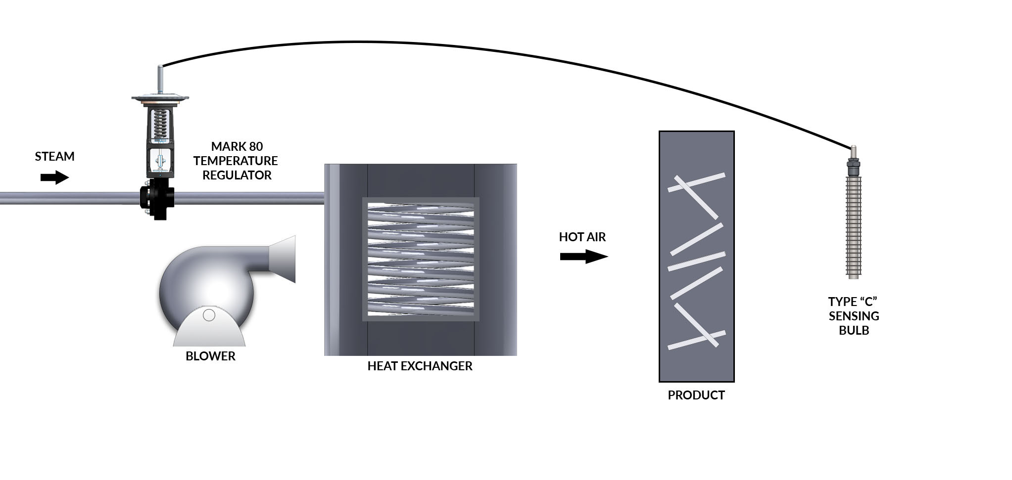
HVAC System Diagram
11. Air Flow Control Valves: Market Trends and Innovations
The automotive industry is continuously evolving, and so are the technologies related to HVAC systems and air flow control valves. Keeping up with the latest market trends and innovations can help automotive technicians and enthusiasts stay ahead of the curve.
11.1. Current Market Trends
-
Increasing Demand for Comfort: As consumer expectations for in-vehicle comfort rise, the demand for advanced HVAC systems with precise air flow control is increasing. This drives the development of more sophisticated and reliable air flow control valves.
-
Energy Efficiency: With growing concerns about fuel efficiency and environmental impact, there is a trend towards energy-efficient HVAC systems. Air flow control valves play a crucial role in optimizing energy usage by directing air only where it is needed.
-
Integration with Smart Technologies: Modern vehicles are increasingly equipped with smart technologies, and HVAC systems are no exception. Air flow control valves are being integrated with smart climate control systems that can automatically adjust airflow based on occupancy, temperature, and other factors.
11.2. Innovations in Air Flow Control Valve Technology
-
Electronic Actuators: Traditional vacuum-operated actuators are being replaced by electronic actuators, which offer greater precision, reliability, and control. Electronic actuators can be controlled by the vehicle’s computer system, allowing for more sophisticated climate control strategies.
-
Brushless DC Motors: Brushless DC motors are being used in air flow control valves to provide quieter operation, longer lifespan, and improved energy efficiency.
-
Smart Actuators: Smart actuators are equipped with sensors and microcontrollers that allow them to monitor their own performance and diagnose potential issues. They can also communicate with the vehicle’s computer system to provide real-time feedback and diagnostic information.
-
Materials and Design: Advances in materials and design are leading to the development of air flow control valves that are more durable, lightweight, and resistant to corrosion and wear.
11.3. Impact on the Automotive Industry
These market trends and innovations are having a significant impact on the automotive industry.
-
Improved HVAC System Performance: Advanced air flow control valve technology is leading to improved HVAC system performance, with more precise temperature control, better airflow distribution, and increased energy efficiency.
-
Enhanced Vehicle Comfort: By providing more comfortable and customizable climate control, advanced HVAC systems are enhancing the overall driving experience.
-
Reduced Environmental Impact: Energy-efficient HVAC systems are helping to reduce the environmental impact of vehicles by lowering fuel consumption and emissions.
By staying informed about the latest market trends and innovations in air flow control valve technology, automotive technicians and enthusiasts can better understand and address the challenges and opportunities in this evolving field. CARDIAGTECH.NET is committed to providing the latest tools, equipment, and information to support the automotive industry in these advancements.
Table 1: Air Flow Control Valve Specifications and Performance
| Feature | Traditional Actuators | Electronic Actuators | Smart Actuators |
|---|---|---|---|
| Control Type | Vacuum | Electronic | Electronic with Sensors |
| Precision | Limited | High | Very High |
| Energy Efficiency | Low | Moderate | High |
| Noise Level | High | Moderate | Low |
| Lifespan | Short | Long | Very Long |
| Diagnostic Capability | None | Limited | Advanced |
| Integration | Basic | Advanced | Full Integration with ECU |
| Typical Applications | Older Vehicles | Modern Vehicles | High-End/Smart Vehicles |
| Estimated Cost | $30 – $80 | $80 – $150 | $150 – $300 |
This table provides a comparison of different types of air flow control valves based on their features, performance, and applications.
For the latest in diagnostic tools and air flow control valve technology, contact CARDIAGTECH.NET via Whatsapp at +1 (641) 206-8880 or visit us at 276 Reock St, City of Orange, NJ 07050, United States.
12. Case Studies: Real-World Air Flow Control Valve Issues
Examining real-world case studies can provide valuable insights into the common issues associated with air flow control valves and how to effectively diagnose and resolve them.
12.1. Case Study 1: Inconsistent Airflow in a 2015 Toyota Camry
Problem: A customer reported that the air conditioning in their 2015 Toyota Camry was only blowing cold air from the driver’s side vents, while the passenger side vents were blowing warm air.
Diagnosis:
- Preliminary Checks: The technician checked the fuses and relays related to the HVAC system and found no issues.
- Scan Tool Diagnostics: A scan tool was used to retrieve DTCs, and code B0446 (Right Temperature Door Actuator Control Circuit Range/Performance) was found.
- Actuator Testing: The technician located the right temperature door actuator and performed electrical testing with a multimeter. The actuator was not receiving the correct signal voltage when the temperature setting was changed.
- Visual Inspection: A visual inspection revealed that the actuator housing was cracked.
Solution: The right temperature door actuator was replaced with a new one from CARDIAGTECH.NET. After replacement, the HVAC system was tested, and the air conditioning was blowing cold air from all vents. The DTC was cleared, and the system was calibrated using a scan tool.
12.2. Case Study 2: Clicking Noise in a 2018 Honda Civic
Problem: A customer complained about a persistent clicking noise coming from under the dashboard of their 2018 Honda Civic, especially when the HVAC system was turned on.
Diagnosis:
- Preliminary Checks: The technician performed a visual inspection and listened to the noise. The clicking sound seemed to be coming from behind the center console.
- Scan Tool Diagnostics: A scan tool was used to retrieve DTCs, and code B0234 (Air Flow Control Actuator Feedback Circuit) was found.
- Actuator Testing: The technician located the air flow control actuator and performed a visual inspection. The actuator linkage was found to be loose.
Solution: The air flow control actuator was replaced. After installation, the clicking noise was gone, and the HVAC system was functioning properly.
12.3. Case Study 3: No Airflow in a 2016 Ford F-150
Problem: A customer reported that there was no airflow coming from any of the vents in their 2016 Ford F-150, regardless of the HVAC settings.
Diagnosis:
- Preliminary Checks: The technician checked the blower motor fuse and relay and found them to be in good condition.
- Scan Tool Diagnostics: A scan tool was used to retrieve DTCs, and code B022