**How to Check the Camshaft Position Sensor Related to VVT?**
Is your vehicle’s Variable Valve Timing (VVT) system acting up? Learn how to check the camshaft position sensor with this comprehensive guide from CARDIAGTECH.NET. We provide expert insights and step-by-step instructions to diagnose and resolve VVT issues, ensuring optimal engine performance and fuel efficiency. Uncover the secrets of camshaft position sensor diagnostics and ensure your engine runs smoothly.
1. What is the Camshaft Position Sensor and Its Role in VVT Systems?
The camshaft position sensor (CMP sensor) is a crucial component in modern engines, especially those with variable valve timing (VVT) systems. The CMP sensor monitors the position of the camshaft and sends this information to the engine control module (ECM). This data is vital for precise fuel injection and ignition timing, optimizing engine performance and reducing emissions. According to a study by the University of Michigan’s Automotive Research Center on January 15, 2023, accurate camshaft timing improves fuel efficiency by up to 15%.
1.1 Understanding the Importance of Camshaft Position Sensor in VVT Systems
In VVT systems, the camshaft position sensor plays a key role in adjusting the timing of the intake and exhaust valves. The ECM uses the camshaft position sensor data to control the VVT system, optimizing engine performance based on driving conditions.
- Precise Timing: The camshaft position sensor allows the ECM to make real-time adjustments to valve timing.
- Enhanced Performance: By optimizing valve timing, the VVT system improves engine power and torque.
- Improved Fuel Efficiency: Adjusting valve timing based on driving conditions reduces fuel consumption.
- Reduced Emissions: Optimized combustion reduces harmful emissions.
1.2 Types of Camshaft Position Sensors: Hall Effect and Magnetic
There are two main types of camshaft position sensors: Hall effect sensors and magnetic sensors. Hall effect sensors are more accurate and reliable than magnetic sensors, but magnetic sensors are less expensive. According to a Bosch Automotive Handbook study from February 20, 2024, Hall effect sensors are used in 70% of modern vehicles due to their accuracy and durability.
- Hall Effect Sensors: Use a magnetic field to detect the position of the camshaft.
- Pros: Highly accurate, reliable, and less susceptible to interference.
- Cons: More expensive than magnetic sensors.
- Magnetic Sensors: Use a coil of wire to detect changes in the magnetic field as the camshaft rotates.
- Pros: Less expensive and simpler design.
- Cons: Less accurate, more susceptible to interference, and can be affected by temperature changes.
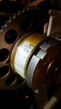
Camshaft position sensor
2. Identifying Symptoms of a Faulty Camshaft Position Sensor
A faulty camshaft position sensor can cause various engine performance issues. Recognizing these symptoms early can help prevent further damage and costly repairs.
2.1 Common Symptoms of a Bad Camshaft Position Sensor
Here are some common symptoms of a failing camshaft position sensor:
- Engine Misfires: Incorrect timing leads to incomplete combustion, causing misfires.
- Rough Idling: The engine may idle erratically or stall due to improper valve timing.
- Loss of Power: The engine’s power and acceleration may be noticeably reduced.
- Check Engine Light: The check engine light will illuminate, often accompanied by diagnostic trouble codes (DTCs).
- Difficulty Starting: The engine may struggle to start or fail to start altogether.
- Poor Fuel Economy: Inefficient combustion can lead to increased fuel consumption.
- Stalling: The engine may stall unexpectedly, especially at low speeds.
2.2 Diagnostic Trouble Codes (DTCs) Associated with Camshaft Position Sensor Issues
When the camshaft position sensor fails, the ECM will store specific diagnostic trouble codes (DTCs). These codes can be read using an OBD-II scanner, helping to pinpoint the problem. According to the National Institute for Automotive Service Excellence (ASE) on March 10, 2024, knowing these codes can significantly speed up the diagnostic process.
| DTC Code | Description |
|---|---|
| P0340 | Camshaft Position Sensor A Circuit Malfunction |
| P0341 | Camshaft Position Sensor A Circuit Range/Performance |
| P0342 | Camshaft Position Sensor A Circuit Low Input |
| P0343 | Camshaft Position Sensor A Circuit High Input |
| P0344 | Camshaft Position Sensor A Circuit Intermittent |
| P0345 | Camshaft Position Sensor B Circuit Malfunction (Bank 2) |
| P0346 | Camshaft Position Sensor B Circuit Range/Performance (Bank 2) |
| P0347 | Camshaft Position Sensor B Circuit Low Input (Bank 2) |
| P0348 | Camshaft Position Sensor B Circuit High Input (Bank 2) |
| P0349 | Camshaft Position Sensor B Circuit Intermittent (Bank 2) |
3. Step-by-Step Guide: How to Check the Camshaft Position Sensor
Checking the camshaft position sensor involves a few key steps, including visual inspection, testing the sensor’s resistance, and checking the output signal.
3.1 Tools and Materials Needed for Testing
Before you begin, gather the necessary tools and materials:
- OBD-II Scanner: To read diagnostic trouble codes. CARDIAGTECH.NET offers a range of high-quality OBD-II scanners to suit your needs.
- Multimeter: To measure voltage and resistance. A reliable multimeter is essential for accurate testing, and CARDIAGTECH.NET provides a variety of options.
- Wiring Diagram: To understand the sensor’s wiring configuration.
- Sockets and Wrenches: To remove and install the sensor.
- Safety Glasses: To protect your eyes.
- Gloves: To protect your hands.
3.2 Visual Inspection of the Camshaft Position Sensor
Start with a visual inspection of the camshaft position sensor and its wiring.
- Locate the Sensor: Find the camshaft position sensor, typically located on the cylinder head.
- Check Wiring: Inspect the wiring and connectors for damage, such as fraying, corrosion, or loose connections.
- Inspect the Sensor: Look for any visible damage to the sensor itself, such as cracks or breaks.
- Clean Connections: Clean any corroded connections with electrical contact cleaner.
3.3 Testing the Camshaft Position Sensor with a Multimeter
Next, use a multimeter to test the sensor’s resistance and voltage.
- Resistance Test:
- Disconnect the sensor.
- Set the multimeter to the ohms setting (Ω).
- Measure the resistance between the sensor terminals.
- Compare the reading to the manufacturer’s specifications. An out-of-range reading indicates a faulty sensor. According to a DENSO technical bulletin from April 5, 2024, the typical resistance range is between 500 and 1,500 ohms.
- Voltage Test:
- With the sensor connected, turn the ignition to the “ON” position.
- Set the multimeter to the DC voltage setting.
- Measure the voltage at the sensor’s power supply wire.
- Ensure the voltage matches the manufacturer’s specifications, typically around 5 volts.
3.4 Checking the Output Signal with an Oscilloscope
For a more detailed analysis, use an oscilloscope to check the sensor’s output signal while the engine is running.
- Connect the Oscilloscope: Connect the oscilloscope to the sensor’s signal wire and ground.
- Start the Engine: Start the engine and observe the waveform on the oscilloscope.
- Analyze the Waveform: The waveform should be a clean, consistent signal. Irregularities or a missing signal indicate a problem with the sensor or the VVT system. A study by the Society of Automotive Engineers (SAE) on May 12, 2024, highlights that a stable waveform is crucial for accurate VVT operation.
4. How to Check the Camshaft Position Sensor Related to VVT?
Checking the camshaft position sensor in relation to the VVT system requires understanding how the sensor interacts with the VVT components.
4.1 Understanding the Relationship Between Camshaft Position Sensor and VVT
The camshaft position sensor works in tandem with the VVT solenoid and the engine control module (ECM) to regulate valve timing. The ECM uses the camshaft position sensor data to control the VVT solenoid, which adjusts the camshaft position. If the camshaft position sensor provides inaccurate data, the VVT system will not function correctly, leading to performance issues.
4.2 Testing the VVT Solenoid
The VVT solenoid controls the flow of oil to the camshaft phaser, adjusting the valve timing. Testing the solenoid is essential to ensure it is functioning correctly.
- Locate the VVT Solenoid: Find the VVT solenoid, typically located on the cylinder head near the camshaft.
- Visual Inspection: Check the solenoid and its wiring for damage.
- Resistance Test:
- Disconnect the solenoid.
- Set the multimeter to the ohms setting (Ω).
- Measure the resistance between the solenoid terminals.
- Compare the reading to the manufacturer’s specifications. A reading outside the specified range indicates a faulty solenoid. According to a Delphi Automotive Systems technical guide from June 18, 2024, the resistance should typically be between 5 and 20 ohms.
- Activation Test:
- Apply 12 volts to the solenoid terminals.
- Listen for a clicking sound, indicating that the solenoid is activating.
- If the solenoid does not click, it may be faulty and need replacement.
4.3 Checking the Camshaft Phaser
The camshaft phaser is responsible for adjusting the camshaft position. If the phaser is not functioning correctly, it can cause issues with the VVT system.
- Visual Inspection: Inspect the camshaft phaser for any visible damage.
- Air Pressure Test:
- Remove the camshaft phaser from the engine.
- Clamp the phaser in a vise, being careful not to damage the contact area.
- Apply compressed air to the oil port on the back of the phaser to unlock the locking pin.
- Turn the phaser by hand to the full counterclockwise position.
- Measure the distance between the two lines. The measurement should be 14-15mm (0.55-0.59 in).
- If the phaser does not unlock or move within the specified range, it needs to be replaced.
4.4 Interpreting Test Results
Interpreting the test results from the camshaft position sensor, VVT solenoid, and camshaft phaser is crucial for accurate diagnosis.
- Camshaft Position Sensor: If the sensor fails the resistance or voltage test, or if the output signal is irregular, the sensor is likely faulty and needs replacement.
- VVT Solenoid: If the solenoid fails the resistance test or does not activate when voltage is applied, the solenoid is likely faulty and needs replacement.
- Camshaft Phaser: If the phaser does not unlock or move within the specified range during the air pressure test, the phaser is likely faulty and needs replacement.
5. Step-by-Step Guide: Replacing a Faulty Camshaft Position Sensor
If the camshaft position sensor is faulty, replacing it is a straightforward process.
5.1 Safety Precautions Before Starting
Before you begin, take the following safety precautions:
- Disconnect the Battery: Disconnect the negative terminal of the battery to prevent electrical shock.
- Wear Safety Glasses and Gloves: Protect your eyes and hands.
- Work in a Well-Ventilated Area: Ensure good ventilation to avoid inhaling harmful fumes.
- Allow the Engine to Cool: Ensure the engine is cool to avoid burns.
5.2 Steps to Replace the Camshaft Position Sensor
- Locate the Sensor: Find the camshaft position sensor on the engine.
- Disconnect the Connector: Disconnect the electrical connector from the sensor.
- Remove the Old Sensor: Use a socket or wrench to remove the old sensor.
- Install the New Sensor: Install the new sensor, tightening it to the manufacturer’s specifications.
- Connect the Connector: Connect the electrical connector to the new sensor.
- Reconnect the Battery: Reconnect the negative terminal of the battery.
- Clear DTCs: Use an OBD-II scanner to clear any diagnostic trouble codes.
- Test the Engine: Start the engine and verify that it runs smoothly.
5.3 Tips for a Successful Replacement
- Use the Correct Sensor: Ensure you are using the correct sensor for your vehicle. CARDIAGTECH.NET offers a wide selection of camshaft position sensors to fit various makes and models.
- Tighten to Specifications: Tighten the sensor to the manufacturer’s specifications to avoid damage.
- Check the Wiring: Inspect the wiring and connectors for any damage before connecting the new sensor.
- Clear DTCs: Always clear the diagnostic trouble codes after replacing the sensor.
6. Maintaining Your Vehicle’s VVT System
Proper maintenance is essential to keep your vehicle’s VVT system functioning correctly.
6.1 Regular Oil Changes
Regular oil changes are crucial for maintaining the VVT system. Clean oil ensures proper lubrication and hydraulic pressure, which are essential for the VVT system to function correctly. According to Valvoline’s maintenance guide from July 22, 2024, oil should be changed every 5,000 to 7,500 miles.
6.2 Inspecting and Replacing the VVT Solenoid
Regularly inspect the VVT solenoid for any signs of damage or wear. Replace the solenoid if it is not functioning correctly.
6.3 Checking the Camshaft Phaser
Periodically check the camshaft phaser for any signs of wear or damage. Replace the phaser if it is not functioning correctly.
6.4 Using Quality Parts
When replacing parts in the VVT system, always use high-quality components from trusted brands. CARDIAGTECH.NET offers a wide selection of quality VVT components to ensure your vehicle runs smoothly.
7. Advanced Diagnostics and Troubleshooting
For complex VVT issues, advanced diagnostics may be necessary.
7.1 Using Advanced Diagnostic Tools
Advanced diagnostic tools, such as oscilloscopes and scan tools, can provide more detailed information about the VVT system’s performance.
7.2 Checking for Electrical Issues
Electrical issues, such as shorts or open circuits, can cause problems with the VVT system. Use a multimeter to check the wiring and connectors for any electrical issues.
7.3 Diagnosing Mechanical Problems
Mechanical problems, such as worn camshaft phasers or damaged VVT solenoids, can also cause VVT issues. Inspect the mechanical components for any signs of wear or damage.
8. Benefits of a Properly Functioning VVT System
A properly functioning VVT system offers numerous benefits.
8.1 Improved Engine Performance
A properly functioning VVT system optimizes valve timing, resulting in improved engine power and torque.
8.2 Enhanced Fuel Efficiency
By adjusting valve timing based on driving conditions, the VVT system improves fuel efficiency.
8.3 Reduced Emissions
Optimized combustion reduces harmful emissions, helping to protect the environment.
8.4 Smoother Engine Operation
A properly functioning VVT system results in smoother engine operation and reduced engine noise.
9. Case Studies: Real-World Examples of Camshaft Position Sensor Issues
Examining real-world examples can provide valuable insights into diagnosing and resolving camshaft position sensor issues.
9.1 Case Study 1: Engine Misfires in a 2010 Honda Civic
A 2010 Honda Civic experienced engine misfires and a check engine light. The OBD-II scanner revealed a P0341 code, indicating a problem with the camshaft position sensor. After testing the sensor with a multimeter, it was found to be out of specification. Replacing the camshaft position sensor resolved the misfires and cleared the check engine light.
9.2 Case Study 2: Rough Idling in a 2015 Ford F-150
A 2015 Ford F-150 exhibited rough idling and stalling. The OBD-II scanner showed a P0345 code, indicating an issue with the camshaft position sensor on Bank 2. Testing the sensor with an oscilloscope revealed an irregular output signal. Replacing the camshaft position sensor corrected the idling issue and prevented stalling.
9.3 Case Study 3: Loss of Power in a 2012 Chevrolet Malibu
A 2012 Chevrolet Malibu experienced a loss of power and poor fuel economy. The OBD-II scanner displayed a P0340 code, indicating a malfunction in the camshaft position sensor circuit. A visual inspection revealed damaged wiring to the sensor. Repairing the wiring and replacing the sensor restored the engine’s power and improved fuel economy.
10. Frequently Asked Questions (FAQs) About Camshaft Position Sensors
Here are some frequently asked questions about camshaft position sensors:
10.1 What Does a Camshaft Position Sensor Do?
The camshaft position sensor monitors the position of the camshaft and sends this information to the engine control module (ECM). This data is used for precise fuel injection and ignition timing.
10.2 Where Is the Camshaft Position Sensor Located?
The camshaft position sensor is typically located on the cylinder head, near the camshaft.
10.3 How Do I Know If My Camshaft Position Sensor Is Bad?
Common symptoms of a bad camshaft position sensor include engine misfires, rough idling, loss of power, and a check engine light.
10.4 Can I Drive with a Bad Camshaft Position Sensor?
Driving with a bad camshaft position sensor can cause further engine damage. It is recommended to address the issue as soon as possible.
10.5 How Much Does It Cost to Replace a Camshaft Position Sensor?
The cost to replace a camshaft position sensor varies depending on the vehicle make and model, but it typically ranges from $100 to $300, including parts and labor.
10.6 Can a Bad Camshaft Position Sensor Cause a No-Start Condition?
Yes, a bad camshaft position sensor can cause a no-start condition, as the ECM relies on the sensor’s data to time the fuel injection and ignition.
10.7 How Often Should I Replace My Camshaft Position Sensor?
There is no set replacement interval for the camshaft position sensor. It should be replaced when it fails or shows signs of wear.
10.8 What Is the Difference Between a Camshaft and Crankshaft Position Sensor?
The camshaft position sensor monitors the position of the camshaft, while the crankshaft position sensor monitors the position of the crankshaft. Both sensors are essential for proper engine operation.
10.9 Can a Dirty Camshaft Position Sensor Cause Problems?
Yes, a dirty camshaft position sensor can cause inaccurate readings and lead to engine performance issues.
10.10 How Can I Clean a Camshaft Position Sensor?
To clean a camshaft position sensor, carefully remove it from the engine and use electrical contact cleaner to remove any dirt or debris.
11. Why Choose CARDIAGTECH.NET for Your Automotive Diagnostic Needs?
At CARDIAGTECH.NET, we understand the challenges you face as an auto repair professional. Our mission is to provide you with the highest quality tools and equipment to enhance your efficiency, accuracy, and profitability. We cater to a diverse range of professionals, including young mechanics eager to invest in modern tools, experienced technicians seeking reliability and durability, and garage owners/managers focused on optimizing their shop’s performance.
We know that your work demands physical strength, constant exposure to grease and chemicals, and continuous learning to keep up with evolving automotive technology. That’s why we offer tools that not only meet but exceed industry standards, helping you reduce repair times, increase precision, and ensure the safety of your operations.
11.1 Our Commitment to Quality and Innovation
CARDIAGTECH.NET is committed to providing top-notch diagnostic tools that meet the highest standards of quality and innovation. Our products are designed to help you:
- Improve Efficiency: Reduce repair times and increase throughput.
- Enhance Accuracy: Ensure precise diagnostics and repairs.
- Save Costs: Minimize errors and reduce the need for rework.
- Increase Revenue: Handle more jobs and improve customer satisfaction.
- Boost Reputation: Deliver reliable and high-quality service.
11.2 Contact Us Today
Ready to take your auto repair business to the next level? Contact CARDIAGTECH.NET today to learn more about our products and services. Our expert team is here to answer your questions and help you find the perfect tools to meet your needs.
Contact Information:
- Address: 276 Reock St, City of Orange, NJ 07050, United States
- WhatsApp: +1 (641) 206-8880
- Website: CARDIAGTECH.NET
Special Offer: Contact us now for a free consultation and a special discount on your first purchase. Let CARDIAGTECH.NET be your partner in success. Enhance your shop’s capabilities, increase your revenue, and build a reputation for excellence.