**How to Check the Manifold Absolute Pressure (MAP) Sensor?**
The Manifold Absolute Pressure (MAP) sensor is crucial for your vehicle’s engine management system, and knowing how to check the MAP sensor can save you time and money. If you’re experiencing issues like poor fuel economy, rough idling, or a check engine light, CARDIAGTECH.NET offers a comprehensive guide and the necessary diagnostic tools to pinpoint the problem. Explore how to test your MAP sensor using both advanced scan tools and multimeters to ensure optimal engine performance and efficiency.
1. What is a Manifold Absolute Pressure (MAP) Sensor?
The Manifold Absolute Pressure (MAP) sensor is a critical component in your vehicle’s engine management system. It measures the pressure inside the intake manifold, providing essential data to the engine control unit (ECU). This information enables the ECU to adjust the air-fuel ratio, ignition timing, and other parameters for optimal engine performance. A properly functioning MAP sensor ensures your engine runs efficiently, delivering the right amount of power while minimizing fuel consumption and emissions.
1.1. Why is the MAP Sensor Important?
The MAP sensor plays a pivotal role in maintaining your engine’s efficiency and performance. According to a study by the U.S. Environmental Protection Agency (EPA), precise air-fuel mixture control can improve fuel economy by up to 15% and reduce harmful emissions significantly. Without accurate data from the MAP sensor, the ECU cannot make these critical adjustments, leading to several problems.
1.2. Potential Issues with a Faulty MAP Sensor
A malfunctioning MAP sensor can cause a range of issues that affect your vehicle’s drivability and fuel efficiency. These problems can include:
- Poor Fuel Economy: The engine may consume more fuel than necessary due to an incorrect air-fuel mixture.
- Rough Idling: The engine may struggle to maintain a smooth idle, leading to vibrations and stalling.
- Loss of Power: The engine may not produce its full power output, resulting in sluggish acceleration and reduced performance.
- Check Engine Light: The ECU may detect abnormal readings from the MAP sensor, triggering the check engine light and storing diagnostic trouble codes (DTCs).
- Increased Emissions: Inefficient combustion can lead to higher levels of harmful emissions, potentially causing your vehicle to fail an emissions test.
1.3. Factors Causing MAP Sensor Failure
Several factors can contribute to the failure of a MAP sensors. Understanding these causes can help you prevent issues.
- Contamination: Over time, the MAP sensor can become contaminated with oil, dirt, and other debris from the intake manifold. This contamination can affect the sensor’s accuracy and responsiveness.
- Electrical Issues: Problems with the sensor’s wiring or connectors, such as corrosion or damage, can disrupt the signal to the ECU.
- Physical Damage: The MAP sensor can be damaged by physical impacts or exposure to extreme temperatures.
- Age and Wear: Like any electronic component, the MAP sensor can degrade over time due to normal wear and tear.
Regular inspection and maintenance of your vehicle’s intake system can help prevent MAP sensor failures.
2. Identifying Symptoms of a Failing MAP Sensor
Recognizing the symptoms of a failing MAP sensor is the first step in diagnosing engine performance issues. Early detection can prevent further damage and ensure timely repairs. Here are the common signs that your MAP sensor may be malfunctioning:
2.1. Decreased Fuel Efficiency
One of the primary indicators of a failing MAP sensor is a noticeable drop in fuel economy. When the MAP sensor provides inaccurate readings, the engine control unit (ECU) might miscalculate the optimal air-fuel ratio. This often leads to an over-rich mixture, where the engine burns more fuel than necessary.
According to a study by Oak Ridge National Laboratory, a poorly calibrated air-fuel mixture can decrease fuel efficiency by as much as 20%. If you find yourself filling up your gas tank more frequently without any changes in your driving habits, it’s time to inspect your MAP sensor.
2.2. Rough or Erratic Idling
A faulty MAP sensor can also cause your engine to idle roughly or erratically. The ECU relies on the MAP sensor to maintain a stable idle speed. When the sensor sends incorrect data, the ECU struggles to regulate the engine’s idle, resulting in:
- Inconsistent RPM: The engine RPM may fluctuate up and down while idling.
- Stalling: The engine may stall, especially when coming to a stop.
- Vibrations: Excessive vibrations can be felt through the steering wheel or seats.
These symptoms are particularly noticeable when the engine is cold, as the ECU depends heavily on sensor data to manage the warm-up process.
2.3. Hesitation During Acceleration
Another common symptom of a failing MAP sensor is hesitation during acceleration. The MAP sensor informs the ECU about changes in engine load, allowing it to adjust the fuel mixture accordingly. If the sensor is not functioning correctly, the ECU may not deliver the right amount of fuel when you press the accelerator pedal. This can result in:
- Delayed Response: A noticeable delay between pressing the accelerator and the engine responding.
- Stuttering: The engine may stutter or stumble during acceleration.
- Lack of Power: The vehicle may feel sluggish and lack its usual power.
These issues can make driving less enjoyable and potentially unsafe, especially when merging onto highways or navigating traffic.
2.4. Check Engine Light Illumination
The most obvious sign of a problem with your MAP sensor is the illumination of the check engine light. When the ECU detects readings from the MAP sensor that are outside of the acceptable range, it will trigger the check engine light and store a diagnostic trouble code (DTC). Common DTCs associated with MAP sensor issues include:
- P0105: Manifold Absolute Pressure/Barometric Pressure Circuit Malfunction
- P0106: Manifold Absolute Pressure/Barometric Pressure Range/Performance Problem
- P0107: Manifold Absolute Pressure/Barometric Pressure Circuit Low Input
- P0108: Manifold Absolute Pressure/Barometric Pressure Circuit High Input
Using a scan tool from CARDIAGTECH.NET to read these codes can provide valuable insights into the nature of the problem.
2.5. Black Smoke from the Exhaust
In some cases, a failing MAP sensor can cause the engine to run excessively rich, leading to black smoke coming from the exhaust. This occurs when the ECU injects too much fuel into the cylinders, resulting in incomplete combustion. The unburned fuel exits the exhaust system as black smoke, which can also produce a strong fuel odor.
According to the California Air Resources Board (CARB), excessive black smoke is a clear indication of a malfunctioning engine management system. Addressing this issue promptly is essential to prevent damage to the catalytic converter and other emissions control components.
By staying vigilant and recognizing these symptoms, you can catch a failing MAP sensor early and take corrective action. This not only improves your vehicle’s performance and fuel efficiency but also helps to prevent more costly repairs down the road. If you notice any of these signs, consider using diagnostic tools from CARDIAGTECH.NET to accurately assess and resolve the issue.
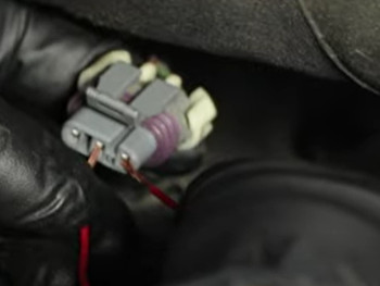
Probing the electrical connector
3. Tools Needed to Check a MAP Sensor
Before you begin testing your MAP sensor, gather the necessary tools to ensure an accurate and efficient diagnosis. Having the right equipment on hand will make the process smoother and help you identify any issues with the sensor. Here’s a list of essential tools for checking a MAP sensor:
3.1. Multimeter or Voltmeter
A multimeter or voltmeter is crucial for testing the electrical signals of the MAP sensor. This tool allows you to measure voltage, current, and resistance, helping you determine if the sensor is receiving the correct power supply and sending the appropriate signals back to the ECU.
- Function: Measures voltage, current, and resistance in electrical circuits.
- Use: Check the voltage supply to the MAP sensor and measure the sensor’s output signal.
- Features to Look For: Digital display, auto-ranging, and overload protection.
3.2. Advanced Scan Tool
An advanced scan tool is invaluable for diagnosing MAP sensor issues. These tools can read diagnostic trouble codes (DTCs), display live sensor data, and perform various diagnostic tests.
- Function: Reads diagnostic trouble codes (DTCs), displays live sensor data, and performs diagnostic tests.
- Use: Retrieve MAP sensor-related DTCs, monitor real-time sensor readings, and graph sensor data to identify intermittent issues.
- Features to Look For: OBD-II compatibility, live data streaming, graphing capabilities, and bidirectional control.
CARDIAGTECH.NET offers a variety of advanced scan tools that are perfect for both professional mechanics and DIY enthusiasts. These tools provide comprehensive diagnostic capabilities, allowing you to quickly and accurately identify issues with your MAP sensor and other engine components.
3.3. Jumper Harness with a Fuse
A jumper harness with a fuse is useful for testing the MAP sensor’s electrical connector. This tool allows you to safely apply power to the sensor and check for proper signal output.
- Function: Provides a safe way to supply power to the MAP sensor for testing.
- Use: Verify that the MAP sensor is receiving the correct voltage and sending a signal back to the ECU.
- Features to Look For: Properly insulated wires, a fuse to protect against shorts, and compatible connectors.
3.4. Wiring Diagram for Your Vehicle
A wiring diagram specific to your vehicle is essential for identifying the correct wires and terminals to test. This diagram provides a detailed layout of the electrical system, including the MAP sensor circuit.
- Function: Provides a detailed layout of the vehicle’s electrical system.
- Use: Identify the correct wires and terminals to test on the MAP sensor and its connector.
- Features to Look For: Vehicle-specific diagrams, clear labeling, and easy-to-read format.
3.5. Basic Hand Tools
In addition to the specialized tools mentioned above, you’ll need some basic hand tools to access and remove the MAP sensor.
- Socket Set: For removing and installing the MAP sensor and any related components.
- Wrench Set: For tightening or loosening bolts and nuts.
- Screwdrivers: For removing any screws securing the MAP sensor or its connector.
- Pliers: For disconnecting hoses or connectors.
3.6. Safety Glasses and Gloves
Safety should always be a priority when working on your vehicle. Protect yourself from potential hazards by wearing safety glasses and gloves.
- Safety Glasses: To protect your eyes from debris or fluids.
- Gloves: To protect your hands from dirt, oil, and chemicals.
Having these tools on hand will ensure that you can effectively and safely check your MAP sensor. CARDIAGTECH.NET offers a wide range of high-quality diagnostic tools and equipment to help you keep your vehicle running smoothly. With the right tools and knowledge, you can diagnose and resolve MAP sensor issues, improving your vehicle’s performance and fuel efficiency.
4. Step-by-Step Guide: Checking the MAP Sensor with a Scan Tool
Using a scan tool is one of the most efficient methods for checking a Manifold Absolute Pressure (MAP) sensor. An advanced scan tool can provide real-time data and diagnostic trouble codes (DTCs), making it easier to identify issues. Here’s a step-by-step guide on how to check the MAP sensor with a scan tool:
4.1. Connect the Scan Tool
The first step is to connect the scan tool to your vehicle’s OBD-II port. This port is typically located under the dashboard on the driver’s side.
- Locate the OBD-II Port: Look for a 16-pin connector, usually near the steering column or under the dash.
- Plug in the Scan Tool: Ensure the scan tool is securely connected to the OBD-II port.
- Power On the Scan Tool: Turn on the scan tool and follow the on-screen instructions to establish a connection with your vehicle’s computer.
4.2. Read Diagnostic Trouble Codes (DTCs)
Once the scan tool is connected, read the diagnostic trouble codes (DTCs) stored in the vehicle’s computer. These codes can provide valuable information about potential issues with the MAP sensor.
- Select “Read Codes”: Navigate through the scan tool’s menu to find the option to read diagnostic trouble codes.
- Record the Codes: Write down any codes related to the MAP sensor, such as P0105, P0106, P0107, or P0108.
- Interpret the Codes: Use the scan tool’s built-in code definitions or consult a reliable online resource to understand the meaning of each code.
4.3. Check the Sitting MAP Sensor Reading
With the vehicle turned on but the engine off, check the MAP sensor reading. This reading should be close to the barometric pressure, which can also be read by the scan tool.
-
Select “Live Data” or “Data Stream”: Navigate to the section of the scan tool that displays real-time sensor data.
-
Find MAP Sensor Data: Locate the MAP sensor reading in the list of available data parameters. It is often labeled as “MAP” or “Manifold Absolute Pressure.”
-
Compare to Barometric Pressure: Check the barometric pressure reading. The MAP sensor reading should be similar, typically around 29 to 30 inches of mercury (inHg) at sea level.
- Acceptable Range: The MAP sensor reading should be within ±1 inHg of the barometric pressure.
- Possible Issue: If the MAP sensor reading is significantly different from the barometric pressure, it may indicate a problem with the sensor.
4.4. Check the Working MAP Sensor Reading
Start the vehicle and observe the MAP sensor reading while the engine is running. The reading should change as you increase or decrease the engine speed.
-
Start the Engine: Start the vehicle and let it idle.
-
Monitor MAP Sensor Data: Watch the MAP sensor reading on the scan tool. At idle, the reading should typically be lower than the sitting reading.
-
Vary Engine Speed: Gently press the accelerator pedal to increase the engine speed, then release it.
-
Observe Changes: The MAP sensor reading should increase as you accelerate and decrease as you release the pedal.
- Normal Operation: The MAP sensor reading should respond quickly and smoothly to changes in engine speed.
- Possible Issue: If the MAP sensor reading does not change or changes erratically, it may indicate a problem with the sensor.
4.5. Graph the MAP Sensor Reading
An advanced scan tool allows you to graph the MAP sensor reading over time. This can help you identify intermittent issues that may not be apparent from simply reading the data.
-
Select “Graphing” Function: Navigate to the graphing function on your scan tool.
-
Choose MAP Sensor Data: Select the MAP sensor data to be graphed.
-
Record Data: Start recording the data while the engine is running. Vary the engine speed to observe the sensor’s response.
-
Analyze the Graph: Look for any spikes, drops, or flat lines in the graph. These can indicate a faulty sensor.
- Normal Operation: The graph should show a smooth, continuous line that corresponds to changes in engine speed.
- Possible Issue: Spikes, drops, or flat lines may indicate a problem with the sensor’s signal.
4.6. Interpret the Results
After completing these steps, interpret the results to determine if the MAP sensor is functioning correctly.
- No DTCs and Normal Readings: If there are no diagnostic trouble codes and the MAP sensor readings are within the expected range, the sensor is likely functioning correctly.
- DTCs and Abnormal Readings: If there are DTCs and the MAP sensor readings are abnormal, the sensor may be faulty and need to be replaced.
By following this step-by-step guide, you can effectively check your MAP sensor with a scan tool and identify any potential issues. CARDIAGTECH.NET offers a wide range of advanced scan tools that can help you diagnose and resolve engine problems quickly and accurately. With the right tools and knowledge, you can keep your vehicle running smoothly and efficiently.
 Graph the MAP Sensor Reading
5. Step-by-Step Guide: Checking the MAP Sensor with a Multimeter
If you don’t have access to an advanced scan tool, you can still check your MAP sensor using a multimeter. This method involves testing the sensor’s electrical connections and voltage output to determine if it’s functioning correctly. Here’s a detailed guide on how to check the MAP sensor with a multimeter:
5.1. Prepare for Testing
Before you begin, gather the necessary tools and information to ensure a safe and accurate testing process.
- Gather Your Tools: Make sure you have a multimeter, wiring diagram for your vehicle, safety glasses, and gloves.
- Locate the MAP Sensor: The MAP sensor is typically located on or near the intake manifold. Consult your vehicle’s repair manual for the exact location.
- Disconnect the Electrical Connector: Carefully disconnect the electrical connector from the MAP sensor.
5.2. Inspect the Electrical Connector
Before testing the sensor, inspect the electrical connector for any signs of damage or corrosion.
- Visual Inspection: Look for any visible signs of corrosion, bent pins, or damaged wires.
- Clean the Connector: If you find any corrosion, clean the connector with electrical contact cleaner.
- Ensure Proper Connection: Make sure the connector is in good condition and will make a secure connection with the MAP sensor.
5.3. Test the Voltage Supply
The first test is to check if the MAP sensor is receiving the correct voltage supply from the vehicle’s computer.
-
Set the Multimeter: Set your multimeter to the DC voltage setting (typically 20V).
-
Identify the Voltage Supply Wire: Consult your vehicle’s wiring diagram to identify the voltage supply wire on the MAP sensor connector. This wire is typically labeled as “VCC” or “+5V.”
-
Connect the Multimeter:
- Connect the positive (red) lead of the multimeter to the voltage supply wire on the connector.
- Connect the negative (black) lead of the multimeter to a known good ground, such as the vehicle’s chassis or battery negative terminal.
-
Turn the Ignition On: Turn the ignition key to the “ON” position, but do not start the engine.
-
Read the Voltage: Observe the voltage reading on the multimeter.
- Normal Operation: The multimeter should read approximately 5 volts.
- Possible Issue: If the voltage reading is significantly higher or lower than 5 volts, it may indicate a problem with the vehicle’s wiring or computer.
5.4. Test the Ground Connection
Next, verify that the MAP sensor has a good ground connection.
-
Identify the Ground Wire: Consult your vehicle’s wiring diagram to identify the ground wire on the MAP sensor connector. This wire is typically labeled as “GND” or “Ground.”
-
Set the Multimeter: Set your multimeter to the continuity setting (or resistance setting if your multimeter does not have a continuity setting).
-
Connect the Multimeter:
- Connect one lead of the multimeter to the ground wire on the connector.
- Connect the other lead to a known good ground, such as the vehicle’s chassis or battery negative terminal.
-
Check for Continuity: Observe the multimeter reading.
- Normal Operation: The multimeter should show continuity (a reading close to 0 ohms), indicating a good ground connection.
- Possible Issue: If the multimeter does not show continuity (a high resistance reading), it may indicate a problem with the ground connection.
5.5. Test the Signal Wire
The final test is to check the signal wire, which carries the MAP sensor’s output signal to the vehicle’s computer.
-
Identify the Signal Wire: Consult your vehicle’s wiring diagram to identify the signal wire on the MAP sensor connector. This wire is typically labeled as “Signal” or “MAP.”
-
Set the Multimeter: Set your multimeter to the DC voltage setting (typically 2V).
-
Connect the Multimeter:
- Connect the positive (red) lead of the multimeter to the signal wire on the connector.
- Connect the negative (black) lead of the multimeter to a known good ground.
-
Turn the Ignition On: Turn the ignition key to the “ON” position, but do not start the engine.
-
Read the Voltage: Observe the voltage reading on the multimeter. The voltage should be within a specific range, typically between 1 and 2 volts, depending on the vehicle.
-
Start the Engine: Start the engine and let it idle.
-
Observe Changes: The voltage reading should change as you increase or decrease the engine speed.
- Normal Operation: The voltage should increase as you accelerate and decrease as you release the pedal.
- Possible Issue: If the voltage reading does not change or changes erratically, it may indicate a problem with the sensor.
5.6. Interpret the Results
After completing these tests, interpret the results to determine if the MAP sensor is functioning correctly.
- Correct Voltage Supply, Good Ground, and Changing Signal: If the voltage supply is correct, the ground connection is good, and the signal voltage changes with engine speed, the MAP sensor is likely functioning correctly.
- Incorrect Voltage Supply, Poor Ground, or No Signal: If the voltage supply is incorrect, the ground connection is poor, or the signal voltage does not change with engine speed, the MAP sensor may be faulty and need to be replaced.
By following this step-by-step guide, you can effectively check your MAP sensor with a multimeter and identify any potential issues.
 Placing spliced wire ends to the outside and center terminal
6. What to Do After Checking the MAP Sensor?
After checking the MAP sensor, the next steps depend on the results of your tests. Whether the sensor is functioning correctly or needs replacement, it’s important to take appropriate actions to ensure your vehicle runs smoothly. Here’s what to do after checking the MAP sensor:
6.1. If the MAP Sensor is Functioning Correctly
If your tests indicate that the MAP sensor is functioning correctly, the issue may lie elsewhere in the engine management system. Here are some steps to take:
- Clear Diagnostic Trouble Codes (DTCs): If you had any DTCs related to the MAP sensor, clear them using your scan tool.
- Check Other Sensors: Investigate other sensors that could be causing similar symptoms, such as the oxygen sensor, throttle position sensor, or mass airflow sensor.
- Inspect Vacuum Lines: Check for any leaks or damage in the vacuum lines, as these can affect engine performance.
- Evaluate Fuel System: Assess the fuel system for issues like a clogged fuel filter, failing fuel pump, or dirty fuel injectors.
- Monitor Performance: Keep an eye on your vehicle’s performance and fuel economy to ensure the problem is resolved.
6.2. If the MAP Sensor Needs Replacement
If your tests indicate that the MAP sensor is faulty, replacement is necessary. Here’s how to proceed:
- Purchase a New MAP Sensor: Buy a replacement MAP sensor from a reputable supplier. Ensure the new sensor is compatible with your vehicle’s make and model. CARDIAGTECH.NET offers a wide selection of high-quality MAP sensors for various vehicles.
- Gather Your Tools: Collect the necessary tools for the replacement, including a socket set, wrench set, screwdrivers, and pliers.
- Disconnect the Battery: Before starting the replacement process, disconnect the negative terminal of your vehicle’s battery to prevent electrical shorts.
- Remove the Old MAP Sensor: Carefully disconnect the electrical connector and any vacuum lines from the old MAP sensor. Use the appropriate tools to remove the sensor from the intake manifold.
- Install the New MAP Sensor: Install the new MAP sensor in the same location as the old one. Ensure it is securely fastened and properly connected.
- Reconnect the Electrical Connector and Vacuum Lines: Reconnect the electrical connector and any vacuum lines to the new MAP sensor.
- Reconnect the Battery: Reconnect the negative terminal of your vehicle’s battery.
- Clear Diagnostic Trouble Codes (DTCs): Use your scan tool to clear any DTCs related to the MAP sensor.
- Test the New MAP Sensor: Start the engine and use your scan tool or multimeter to verify that the new MAP sensor is functioning correctly.
- Monitor Performance: Take your vehicle for a test drive and monitor its performance and fuel economy.
6.3. Tips for Replacing the MAP Sensor
Replacing the MAP sensor is a straightforward task, but here are some tips to ensure a successful replacement:
- Use Quality Parts: Always use high-quality replacement parts from reputable suppliers like CARDIAGTECH.NET to ensure optimal performance and reliability.
- Follow the Service Manual: Refer to your vehicle’s service manual for specific instructions and torque specifications.
- Handle with Care: Handle the MAP sensor with care to avoid damaging the delicate components.
- Clean the Mounting Surface: Before installing the new MAP sensor, clean the mounting surface on the intake manifold to ensure a good seal.
- Properly Seat the Connector: Make sure the electrical connector is fully seated and securely fastened to the MAP sensor.
By following these steps, you can effectively replace your MAP sensor and restore your vehicle’s performance and fuel efficiency. CARDIAGTECH.NET provides the tools, parts, and resources you need to keep your vehicle running smoothly.
7. Maintaining Your MAP Sensor for Longevity
Proper maintenance is essential for ensuring the longevity and reliability of your MAP sensor. Regular checks and preventive measures can help you avoid costly repairs and keep your vehicle running efficiently. Here are some tips for maintaining your MAP sensor:
7.1. Regular Inspections
Perform regular visual inspections of the MAP sensor and its connections. Look for signs of damage, corrosion, or contamination.
- Frequency: Check the MAP sensor every 6 months or during your regular maintenance intervals.
- What to Look For:
- Cracks or damage to the sensor body.
- Corrosion on the electrical connector pins.
- Loose or damaged vacuum lines.
- Oil or dirt buildup on the sensor.
7.2. Keep the Engine Clean
A clean engine bay can help prevent contamination of the MAP sensor. Regularly clean the engine bay to remove dirt, oil, and debris.
- How to Clean: Use a mild degreaser and a soft brush to clean the engine bay. Avoid spraying water directly onto the MAP sensor or other electrical components.
- Benefits:
- Reduces the risk of contamination.
- Helps prevent corrosion.
- Makes it easier to identify leaks and other issues.
7.3. Replace Air Filters Regularly
A clean air filter is essential for preventing dirt and debris from entering the intake manifold and contaminating the MAP sensor.
- Frequency: Replace the air filter according to the manufacturer’s recommended service intervals.
- Benefits:
- Ensures clean air flows to the engine.
- Prevents dirt and debris from contaminating the MAP sensor.
- Improves engine performance and fuel efficiency.
7.4. Use High-Quality Fuel
Using high-quality fuel can help prevent the buildup of deposits in the intake manifold, which can contaminate the MAP sensor.
- Fuel Type: Use the fuel grade recommended by the manufacturer.
- Benefits:
- Reduces the risk of deposit buildup.
- Helps keep the fuel system clean.
- Ensures optimal engine performance.
7.5. Check and Replace Vacuum Lines
Vacuum lines connect to the MAP sensor and play a crucial role in its operation. Check the vacuum lines regularly for cracks, leaks, or damage.
- Frequency: Check the vacuum lines every 6 months or during your regular maintenance intervals.
- What to Look For:
- Cracks or splits in the lines.
- Loose or disconnected lines.
- Hard or brittle lines.
- Replacement: Replace any damaged or deteriorated vacuum lines immediately.
7.6. Avoid Over-Oiling Air Filters
If you use an oiled air filter, be careful not to over-oil it. Excess oil can get into the intake manifold and contaminate the MAP sensor.
- Proper Oiling: Follow the manufacturer’s instructions for oiling the air filter.
- Benefits:
- Prevents excess oil from entering the intake manifold.
- Ensures the MAP sensor remains clean and functional.
7.7. Monitor Engine Performance
Keep an eye on your vehicle’s performance and fuel economy. Any sudden changes could indicate a problem with the MAP sensor or other engine components.
- What to Watch For:
- Decreased fuel efficiency.
- Rough idling.
- Hesitation during acceleration.
- Illumination of the check engine light.
- Action: If you notice any of these symptoms, check the MAP sensor and other engine components promptly.
By following these maintenance tips, you can extend the life of your MAP sensor and keep your vehicle running smoothly. CARDIAGTECH.NET offers a wide range of diagnostic tools and replacement parts to help you maintain your vehicle’s engine management system. Regular maintenance not only improves your vehicle’s performance and fuel efficiency but also helps to prevent more costly repairs down the road.
8. Common Mistakes to Avoid When Checking a MAP Sensor
Checking a MAP sensor can be a straightforward process, but it’s essential to avoid common mistakes that can lead to inaccurate diagnoses or damage to the sensor. Here are some common pitfalls to watch out for when checking a MAP sensor:
8.1. Not Disconnecting the Battery
Failing to disconnect the battery before working on the electrical system is a common mistake. This can lead to electrical shorts, damage to the sensor, or even injury.
- Why It’s Important: Disconnecting the battery ensures that there is no power flowing through the system, reducing the risk of electrical accidents.
- Best Practice: Always disconnect the negative terminal of the battery before checking or replacing the MAP sensor.
8.2. Using the Wrong Tools
Using the wrong tools can damage the MAP sensor or its connections. For example, using pliers instead of a socket wrench can strip the sensor’s mounting bolts.
- Why It’s Important: Using the correct tools ensures that you can perform the job safely and effectively without damaging any components.
- Best Practice: Use the appropriate socket set, wrench set, screwdrivers, and pliers for the job.
8.3. Not Consulting the Wiring Diagram
Failing to consult the vehicle’s wiring diagram can lead to testing the wrong wires or making incorrect connections.
- Why It’s Important: The wiring diagram provides a detailed layout of the electrical system, including the MAP sensor circuit, helping you identify the correct wires and terminals.
- Best Practice: Always refer to the vehicle’s wiring diagram before testing the MAP sensor.
8.4. Ignoring Visual Inspections
Skipping the visual inspection of the MAP sensor and its connections can cause you to miss obvious signs of damage or corrosion.
- Why It’s Important: Visual inspections can reveal issues such as cracked sensors, corroded connectors, or damaged wires that can affect the sensor’s performance.
- Best Practice: Always perform a thorough visual inspection before conducting any electrical tests.
8.5. Not Cleaning the Connector
If the electrical connector is dirty or corroded, it can interfere with the sensor’s signal.
- Why It’s Important: A clean connector ensures a good electrical connection between the MAP sensor and the vehicle’s computer.
- Best Practice: Clean the connector with electrical contact cleaner before testing the MAP sensor.
8.6. Overtightening Mounting Bolts
Overtightening the MAP sensor’s mounting bolts can damage the sensor or the intake manifold.
- Why It’s Important: Overtightening can strip the threads or crack the sensor body, leading to leaks or sensor failure.
- Best Practice: Tighten the mounting bolts to the manufacturer’s specified torque. If you don’t have the torque specification, tighten the bolts snugly but not excessively.
8.7. Not Clearing Diagnostic Trouble Codes (DTCs)
Failing to clear the DTCs after replacing the MAP sensor can cause confusion and make it difficult to diagnose future issues.
- Why It’s Important: Clearing the DTCs resets the vehicle’s computer and allows it to relearn the new sensor’s readings.
- Best Practice: Use your scan tool to clear any DTCs related to the MAP sensor after replacement.
8.8. Neglecting Vacuum Lines
Ignoring the condition of the vacuum lines can lead to inaccurate MAP sensor readings.
- Why It’s Important: Vacuum lines connect to the MAP sensor and play a crucial role in its operation. Leaks or damage in the vacuum lines can affect the sensor’s performance.
- Best Practice: Check the vacuum lines regularly for cracks, leaks, or damage, and replace them as needed.
By avoiding these common mistakes, you can ensure an accurate diagnosis and prevent damage to the MAP sensor or other components. CARDIAGTECH.NET offers a wide range of diagnostic tools and replacement parts to help you maintain your vehicle’s engine management system effectively.
9. Frequently Asked Questions (FAQs) About MAP Sensors
Here are some frequently asked questions about MAP sensors to help you better understand their function, diagnosis, and maintenance:
9.1. What does a MAP sensor do?
The MAP (Manifold Absolute Pressure) sensor measures the pressure in the intake manifold of an engine. This information is used by the engine control unit (ECU) to determine the engine’s air-fuel ratio, ignition timing, and other parameters for optimal performance.
9.2. Where is the MAP sensor located?
The MAP sensor is typically located on or near the intake manifold of the engine. Its exact location can vary depending on the vehicle make and model. Consult your vehicle’s repair manual for specific information.
9.3. How do I know if my MAP sensor is bad?
Common symptoms of a bad MAP sensor include decreased fuel efficiency, rough or erratic idling, hesitation during acceleration, illumination of the check engine light, and black smoke from the exhaust.
9.4. Can I drive with a bad MAP sensor?
While it is possible to drive with a bad MAP sensor, it is not recommended. A faulty MAP sensor can cause poor engine performance, reduced fuel efficiency, and potential damage to other engine components.
9.5. How much does it cost to replace a MAP sensor?
The cost to replace a MAP sensor can vary depending on the vehicle make and model, as well as the cost of labor. Generally, the cost ranges from $100 to $300, including parts and labor.
9.6. Can a bad MAP sensor cause a no-start condition?
Yes, in some cases, a bad MAP sensor can cause a no-start condition. If the MAP sensor provides incorrect data to the ECU, the engine may not receive the correct air-fuel mixture to start.
9.7. How often should I replace my MAP sensor?
There is no specific replacement interval for MAP sensors. However, it is recommended to inspect the MAP sensor regularly and replace it if you notice any signs of failure or performance issues.
9.8. Can a dirty air filter affect the MAP sensor?
Yes, a dirty air filter can affect the MAP sensor. A dirty air filter can restrict airflow to the engine, causing a vacuum imbalance that can affect the MAP sensor’s readings.
9.9. Is it difficult to replace a MAP sensor?
Replacing a MAP sensor is generally a straightforward task that can be done with basic hand tools. However, it is important to consult your vehicle’s repair manual for specific instructions and