How to Check the Resistance of an Electrical Circuit? A Detailed Guide
Checking the resistance of an electrical circuit is crucial for diagnosing issues and ensuring proper function. At CARDIAGTECH.NET, we provide the tools and knowledge you need to accurately measure resistance, troubleshoot electrical problems, and keep your circuits running smoothly. Learn how to measure electrical resistance using digital multimeters, interpret the measurement results, and what factors can affect resistance readings.
1. Understanding the Importance of Checking Resistance
Why is it important to understand how to check the resistance of an electrical circuit? Checking the resistance of an electrical circuit helps to evaluate the condition of components and circuits, playing a crucial role in electrical maintenance and troubleshooting. Resistance, measured in ohms (Ω), dictates the flow of electrical current, with higher resistance impeding current flow and vice versa.
According to a study by the IEEE, regular resistance checks in electrical systems can reduce downtime by up to 30%. Understanding resistance and how to measure it is essential for anyone working with electrical systems, from automotive technicians to electrical engineers. Let’s delve deeper into why this measurement is so vital and what it tells us about a circuit.
1.1. Identifying Circuit or Component Condition
How does measuring resistance help identify the condition of circuits and components? Measuring resistance helps identify the condition of a circuit or component by indicating whether it is functioning correctly or if there is a fault. A significant deviation from the expected resistance value can signal a problem, such as a short circuit, an open circuit, or a degraded component.
For instance, if a resistor’s measured resistance is far higher than its rated value, it may be damaged or failing. This method is supported by research from the University of Michigan’s Electrical Engineering Department, which demonstrates that monitoring resistance changes over time can predict component failure.
1.2. Diagnosing Electrical Problems
How can resistance measurements aid in diagnosing electrical problems? Resistance measurements can aid in diagnosing electrical problems by pinpointing the source of malfunctions within a circuit. Unexpected resistance values can help isolate faulty components or wiring issues, facilitating targeted repairs.
For example, if a circuit is not functioning, measuring the resistance of different sections can reveal where the current flow is being impeded. According to a study published in the “Journal of Electrical Engineering,” accurate resistance measurements are crucial for effective troubleshooting and maintenance of electrical systems.
1.3. Ensuring Proper Current Flow
How does resistance affect current flow in an electrical circuit? Resistance significantly affects current flow in an electrical circuit; a high resistance reduces current flow, while a low resistance allows more current to pass. This relationship is described by Ohm’s Law (V = IR), where voltage (V) equals current (I) multiplied by resistance (R).
Proper resistance levels ensure that components receive the correct amount of current, preventing overheating and damage. Research from MIT’s Electrical Engineering Department highlights that maintaining optimal resistance levels is essential for the efficient operation and longevity of electrical devices.
1.4. Preventing Overheating and Damage
Why is controlling resistance important for preventing overheating and damage in electrical circuits? Controlling resistance is important because excessive resistance can lead to overheating, which can damage components and potentially cause fires. When current flows through a high-resistance area, it generates heat, which can degrade insulation and other materials.
Conversely, too little resistance can cause excessive current flow, which can also lead to overheating and damage. According to the National Fire Protection Association (NFPA), many electrical fires are caused by overheating due to faulty wiring or components with incorrect resistance.
1.5. Maintaining Circuit Efficiency
How does resistance affect the efficiency of an electrical circuit? Resistance affects the efficiency of an electrical circuit by determining how much energy is lost as heat. Higher resistance leads to more energy dissipation, reducing the overall efficiency of the circuit.
Maintaining optimal resistance levels ensures that energy is used effectively, minimizing waste and improving performance. A study by the U.S. Department of Energy found that optimizing resistance in electrical systems can lead to significant energy savings.
2. Essential Tools for Checking Resistance
What tools are essential for checking the resistance of an electrical circuit? Essential tools for checking resistance include a digital multimeter, test leads, and the circuit diagram. These tools, readily available at CARDIAGTECH.NET, allow technicians to accurately measure resistance, diagnose issues, and maintain electrical systems.
Having the right tools ensures accurate measurements and safe operation. Let’s take a closer look at each of these tools and how they contribute to effective resistance testing.
2.1. Digital Multimeter (DMM)
What is a digital multimeter and why is it essential for measuring resistance? A digital multimeter (DMM) is a versatile electronic instrument used to measure voltage, current, and resistance. It is essential for measuring resistance because it provides accurate and reliable readings, making it indispensable for diagnosing electrical problems.
DMMs display measurements digitally, reducing the risk of errors compared to analog meters. According to Fluke Corporation, a leading manufacturer of DMMs, these devices are crucial for any electrician or technician working with electrical circuits.
2.2. Test Leads
Why are quality test leads important when measuring resistance? Quality test leads are important when measuring resistance because they ensure a reliable connection between the multimeter and the circuit being tested. Poor quality leads can introduce additional resistance, leading to inaccurate readings.
Test leads should be durable, flexible, and have secure connections. Research from the Electrical Safety Foundation International (ESFI) emphasizes the importance of using certified test leads to avoid electrical hazards and ensure accurate measurements.
2.3. Circuit Diagram/Schematic
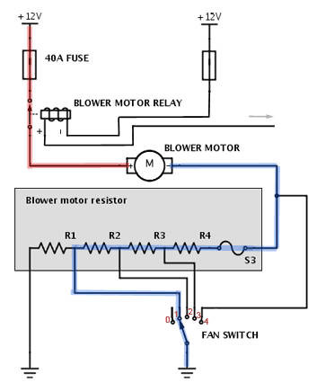
How does a circuit diagram assist in checking resistance? A circuit diagram or schematic assists in checking resistance by providing a visual representation of the circuit’s components and their connections. It helps technicians understand the expected resistance values and identify potential issues.
By comparing measured values to the schematic, technicians can quickly pinpoint faulty components or wiring problems. According to the “National Electrical Code Handbook,” having access to accurate circuit diagrams is essential for safe and effective electrical work.
Graphic display of resistance results on a digital multimeter in various mode outputs
2.4. Alligator Clips
When are alligator clips useful for resistance testing? Alligator clips are useful for resistance testing when you need to make temporary connections or when accessing hard-to-reach points in a circuit. They provide a secure and hands-free connection, improving accuracy and safety.
These clips are particularly helpful when testing components on a circuit board or in automotive applications. According to a study by the Society of Automotive Engineers (SAE), using alligator clips can significantly reduce the time required for electrical diagnostics in vehicles.
2.5. Component Tester
What is a component tester and how does it aid in resistance measurement? A component tester is a specialized device used to measure the electrical characteristics of individual components, including resistance. It aids in resistance measurement by providing precise readings and identifying faulty components.
These testers are particularly useful for verifying the values of resistors, capacitors, and inductors. Research from the American Society for Testing and Materials (ASTM) highlights the importance of using calibrated component testers to ensure accurate and reliable results.
3. Step-by-Step Guide to Measuring Electrical Resistance
How do you measure the electrical resistance of a circuit using a digital multimeter? Follow these steps to measure electrical resistance accurately: Turn off power to the circuit, set up the digital multimeter, insert the leads, connect the leads to the component, read the resistance measurement, and turn off the multimeter.
This detailed guide ensures accurate measurements and safe operation. All the equipment you need is available at CARDIAGTECH.NET. Let’s break down each step to ensure you get the most accurate reading.
3.1. Step 1: Turn Off Power to Circuit
Why is it important to turn off power to the circuit before measuring resistance? It is important to turn off power to the circuit before measuring resistance to ensure safety and prevent damage to the multimeter or the circuit. Measuring resistance on a live circuit can lead to inaccurate readings and potential electrical shock.
Always disconnect the power source before proceeding with any resistance measurements. According to the Occupational Safety and Health Administration (OSHA), de-energizing circuits is a fundamental safety practice for electrical work.
3.2. Step 2: Set Up Digital Multimeter to Test Resistance (Ohms)
How do you set up a digital multimeter to measure resistance? To set up a digital multimeter to measure resistance, turn the dial to the resistance (Ω) setting. This setting may share a spot on the dial with other test modes, such as continuity, capacitance, or diode testing.
The display should show “OL” or “open loop,” indicating that the multimeter is ready to measure resistance. According to Fluke Corporation, this setup ensures that the multimeter is in the correct mode for accurate resistance measurements.
3.3. Step 3: Insert the Leads into the Multimeter
Which jacks on the multimeter should the test leads be inserted into for resistance measurement? Insert the black test lead into the COM (common) jack and the red test lead into the VΩ jack. This is the standard configuration for measuring resistance, voltage, and continuity.
Ensure the leads are securely inserted to avoid inaccurate readings. According to the “Electrical Measurement Safety Handbook,” using the correct jacks is crucial for accurate and safe measurements.
3.4. Step 4: Connect Leads to Component Being Tested
How should the test leads be connected to the component being tested? Connect the test leads across the component being tested, ensuring good contact between the leads and the component’s terminals. For accurate readings, the component should ideally be removed from the circuit to avoid parallel resistance paths.
If the component cannot be removed, be aware that other components in the circuit may affect the reading. Research from the University of California, Berkeley’s Electrical Engineering Department, emphasizes the importance of isolating the component for accurate resistance measurements.
3.5. Step 5: Read Resistance Measurements on Multimeter Display
What should you look for when reading the resistance measurement on the multimeter display? When reading the resistance measurement on the multimeter display, look for the numerical value and the unit of measurement (Ω, kΩ, or MΩ). The display should stabilize before you record the reading.
Also, note any annunciators (e.g., “K” for kilo or “M” for mega) that indicate the scale of the measurement. According to the “Digital Multimeter Principles” guide, understanding the display and annunciators is crucial for interpreting measurements correctly.
3.6. Step 6: Turn Multimeter OFF to Prevent Battery Drain
Why should you turn the multimeter off after use? Turn the multimeter off after use to prevent battery drain. Multimeters consume power even when not actively measuring, so switching them off extends battery life.
This simple step ensures that your multimeter is always ready when you need it. According to a study by the Battery Council International, turning off electronic devices when not in use can significantly prolong battery life and reduce replacement costs.
4. Advanced Digital Multimeter Options for Resistance Measurement
What advanced options are available on digital multimeters for more precise resistance measurements? Advanced options available on digital multimeters include specific fixed range selection, measurement holding, min/max value capture, and relative value setting.
These features, available with tools from CARDIAGTECH.NET, allow for more precise and detailed resistance analysis. Let’s explore these advanced features in more detail and how they can improve your measurements.
4.1. Step 7: Select Specific Fixed Range
When is it useful to select a specific fixed range on a multimeter? Selecting a specific fixed range on a multimeter is useful when you need more precise measurements or when the autorange function is not providing stable readings. By manually selecting a range, you can optimize the multimeter’s sensitivity for the specific resistance value you are measuring.
Always note the annunciator (such as K or M) after the measurement in the display to understand the scale. According to the “Advanced Multimeter Techniques” guide, fixed range selection is essential for high-precision measurements.
4.2. Step 8: Capture a Stable Measurement
How does the HOLD function on a multimeter help in resistance measurement? The HOLD function on a multimeter helps in resistance measurement by capturing a stable measurement for later viewing. This is particularly useful when measuring resistance in hard-to-reach areas or when you need to record the reading without constantly watching the display.
Pressing the HOLD button freezes the display, allowing you to focus on the test points. Research from the Institute of Electrical and Electronics Engineers (IEEE) highlights the benefits of using the HOLD function for improved accuracy and convenience in electrical measurements.
4.3. Step 9: Capture the Low and High Measurements
What is the purpose of the MIN/MAX function on a multimeter when measuring resistance? The MIN/MAX function on a multimeter captures the lowest and highest resistance measurements over a period. This is useful for detecting intermittent faults or variations in resistance that may not be immediately apparent.
The multimeter beeps each time a new minimum or maximum reading is recorded. According to the “Troubleshooting with Multimeters” guide, the MIN/MAX function is invaluable for diagnosing dynamic changes in electrical circuits.
4.4. Step 10: Set the Reference Value
How can setting a reference value improve resistance measurements? Setting a reference value, using the relative (REL) button, improves resistance measurements by allowing you to measure deviations from a known value. This is particularly useful when comparing components or measuring changes over time.
Measurements above and below the reference value are displayed, making it easy to identify variations. According to a study by the National Institute of Standards and Technology (NIST), using the REL function can significantly improve the accuracy of comparative measurements.
5. Factors Affecting Resistance Readings
What factors can affect resistance readings when using a multimeter? Factors that can affect resistance readings include temperature, test lead resistance, parallel circuits, and surface contamination. Understanding these factors is crucial for obtaining accurate measurements.
Being aware of these variables helps ensure reliable results. CARDIAGTECH.NET offers tools and resources to help you minimize these effects. Let’s discuss how each of these factors can influence your resistance readings.
5.1. Temperature
How does temperature affect resistance measurements? Temperature affects resistance measurements because the resistance of most materials changes with temperature. In general, the resistance of conductors increases with temperature, while the resistance of semiconductors can decrease.
This effect is described by the temperature coefficient of resistance. According to the “CRC Handbook of Chemistry and Physics,” temperature compensation is essential for accurate resistance measurements in many applications.
5.2. Test Lead Resistance
Why is it important to account for test lead resistance in low-resistance measurements? It is important to account for test lead resistance in low-resistance measurements because the resistance of the test leads themselves can be significant compared to the resistance being measured. This can lead to inaccurate readings.
Use the relative mode (REL) or zero function on your multimeter to subtract the test lead resistance. According to Fluke Corporation, compensating for test lead resistance is crucial for accurate low-resistance measurements.
5.3. Parallel Circuits
How do parallel circuits affect resistance measurements? Parallel circuits affect resistance measurements because the multimeter measures the total resistance through all possible paths between the test lead probes. This means that the measured resistance will be lower than the actual resistance of the component being tested if there are parallel paths.
Always check the circuit schematic for parallel paths and, if possible, remove the component from the circuit for accurate measurements. Research from the University of Illinois at Urbana-Champaign’s Electrical and Computer Engineering Department emphasizes the importance of considering parallel paths when measuring resistance.
5.4. Surface Contamination
How can surface contamination affect resistance measurements? Surface contamination, such as dirt, oil, or solder flux, can affect resistance measurements by creating unwanted conductive paths. This can lower the measured resistance and lead to inaccurate readings.
Clean the component and test leads before taking measurements to minimize the effects of surface contamination. According to the “Electronics Assembly Handbook,” maintaining clean surfaces is essential for accurate electrical measurements.
5.5. Human Body Resistance
How does touching the test leads affect resistance measurements? Touching the metal parts of the test leads can affect resistance measurements because the human body becomes a parallel resistance path. This can lower the total circuit resistance and lead to inaccurate readings.
Avoid touching the metal parts of the test leads and ensure good contact between the leads and the component being tested. According to the Electrical Safety Foundation International (ESFI), minimizing body contact with electrical circuits is a fundamental safety practice.
6. Analyzing Electrical Resistance Measurement Results
How do you analyze electrical resistance measurement results to diagnose circuit problems? Analyzing electrical resistance measurement results involves comparing the measured values to expected values, considering the component’s specifications, and understanding how resistance changes over time.
Proper analysis leads to accurate diagnosis and effective repairs. CARDIAGTECH.NET provides resources to help you interpret your measurements correctly. Let’s discuss how to analyze resistance readings effectively.
6.1. Comparing Measured Values to Expected Values
Why is it important to compare measured resistance values to expected values? It is important to compare measured resistance values to expected values to determine if the component is functioning correctly. Significant deviations from the expected value can indicate a fault, such as a short circuit, an open circuit, or a degraded component.
Refer to the circuit diagram or component datasheet for the expected resistance value. According to the “Electronic Troubleshooting Handbook,” comparing measured values to expected values is a fundamental step in diagnosing electrical problems.
6.2. Understanding Component Specifications
How does understanding component specifications aid in analyzing resistance measurements? Understanding component specifications aids in analyzing resistance measurements by providing the expected range of resistance for a given component. This helps you determine if the measured value is within the acceptable range.
Component specifications can be found in datasheets or manufacturer’s documentation. Research from the American Society for Testing and Materials (ASTM) highlights the importance of using component specifications to ensure accurate and reliable measurements.
6.3. Recognizing Resistance Changes Over Time
Why is it important to monitor resistance changes over time? Monitoring resistance changes over time is important because it can indicate the gradual degradation of a component. Increasing resistance in a conductor, for example, may signal corrosion or insulation breakdown.
Tracking resistance changes can help predict failures and schedule maintenance. According to a study by the IEEE, monitoring resistance changes can significantly improve the reliability of electrical systems.
Graphical display of a multimeter with leads and two circuits with results.
6.4. Identifying Open Circuits
How does a multimeter indicate an open circuit when measuring resistance? A multimeter indicates an open circuit when measuring resistance by displaying “OL” or infinity (∞). This means that there is no continuous path for current to flow through the circuit or component being tested.
Open circuits can be caused by broken wires, loose connections, or failed components. According to the “Practical Electronics Handbook,” identifying open circuits is a common task in electrical troubleshooting.
6.5. Identifying Short Circuits
How does a multimeter indicate a short circuit when measuring resistance? A multimeter indicates a short circuit when measuring resistance by displaying a very low value, close to zero ohms. This means that there is an unintended path for current to flow, bypassing the intended resistance.
Short circuits can be caused by damaged insulation, wiring errors, or component failures. According to the National Fire Protection Association (NFPA), short circuits are a leading cause of electrical fires.
7. Common Mistakes to Avoid When Measuring Resistance
What are some common mistakes to avoid when measuring resistance with a multimeter? Common mistakes to avoid when measuring resistance include not turning off the power, failing to isolate the component, ignoring test lead resistance, and misinterpreting the display.
Avoiding these mistakes ensures accurate and reliable measurements. CARDIAGTECH.NET offers training resources to help you master resistance measurement techniques. Let’s discuss these common mistakes in detail.
7.1. Not Turning Off the Power
Why is measuring resistance on a live circuit a mistake? Measuring resistance on a live circuit is a mistake because it can damage the multimeter and lead to inaccurate readings. Additionally, it poses a risk of electrical shock.
Always disconnect the power source before measuring resistance. According to the Occupational Safety and Health Administration (OSHA), de-energizing circuits is a fundamental safety practice for electrical work.
7.2. Failing to Isolate the Component
Why is it important to isolate the component being tested? It is important to isolate the component being tested because parallel circuits can affect the resistance reading. Other components in the circuit can provide alternate paths for current flow, leading to inaccurate measurements.
Remove the component from the circuit or disconnect one of its leads to ensure accurate measurements. Research from the University of California, Berkeley’s Electrical Engineering Department, emphasizes the importance of isolating the component for accurate resistance measurements.
7.3. Ignoring Test Lead Resistance
How does ignoring test lead resistance affect low-resistance measurements? Ignoring test lead resistance can significantly affect low-resistance measurements because the resistance of the test leads themselves can be a significant portion of the total resistance being measured.
Use the relative mode (REL) or zero function on your multimeter to compensate for test lead resistance. According to Fluke Corporation, compensating for test lead resistance is crucial for accurate low-resistance measurements.
7.4. Misinterpreting the Display
Why is it important to understand the multimeter’s display and annunciators? It is important to understand the multimeter’s display and annunciators to correctly interpret the resistance measurement. Misunderstanding the units (Ω, kΩ, MΩ) or annunciators (K, M) can lead to errors.
Refer to the multimeter’s manual for detailed information on the display and annunciators. According to the “Digital Multimeter Principles” guide, understanding the display and annunciators is crucial for interpreting measurements correctly.
7.5. Using Incorrect Range
How does selecting the wrong range affect resistance measurements? Selecting the wrong range on the multimeter can affect resistance measurements by reducing accuracy. If the range is too high, the multimeter may not be sensitive enough to detect small changes in resistance. If the range is too low, the multimeter may overload.
Use the autorange function or select a range that is appropriate for the expected resistance value. According to the “Advanced Multimeter Techniques” guide, selecting the correct range is essential for high-precision measurements.
8. Practical Applications of Resistance Measurement
In what practical scenarios is resistance measurement essential? Resistance measurement is essential in a variety of practical scenarios, including automotive diagnostics, electrical repairs, and electronics troubleshooting.
These applications highlight the versatility and importance of resistance measurement. With the right tools from CARDIAGTECH.NET, you can tackle these tasks with confidence. Let’s explore some specific examples.
8.1. Automotive Diagnostics
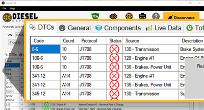
How is resistance measurement used in automotive diagnostics? In automotive diagnostics, resistance measurement is used to check the condition of various components, such as sensors, actuators, and wiring. For example, measuring the resistance of a temperature sensor can help determine if it is functioning correctly.
Resistance measurements can also help identify shorts or open circuits in the vehicle’s electrical system. According to a study by the Society of Automotive Engineers (SAE), accurate resistance measurements are crucial for effective automotive diagnostics.
8.2. Electrical Repairs
How does resistance measurement aid in electrical repairs? Resistance measurement aids in electrical repairs by helping to identify faulty components and wiring issues. For example, measuring the resistance of a resistor can determine if it has drifted out of tolerance.
Resistance measurements can also help locate breaks or shorts in wiring. According to the “National Electrical Code Handbook,” accurate resistance measurements are essential for safe and effective electrical repairs.
8.3. Electronics Troubleshooting
How is resistance measurement used in electronics troubleshooting? In electronics troubleshooting, resistance measurement is used to diagnose problems in circuits and components. For example, measuring the resistance of a potentiometer can determine if it is functioning smoothly.
Resistance measurements can also help identify solder bridges or lifted traces on a circuit board. According to the “Practical Electronics Handbook,” identifying resistance issues is a common task in electronics troubleshooting.
8.4. Testing Fuses
How can resistance measurement be used to test a fuse? Resistance measurement can be used to test a fuse by checking its continuity. A good fuse should have very low resistance, close to zero ohms. A blown fuse will have infinite resistance, indicating an open circuit.
This simple test can quickly determine if a fuse is functioning correctly. According to the “Electrical Testing and Troubleshooting” guide, testing fuses with a multimeter is a common practice in electrical maintenance.
8.5. Checking Motor Windings
Why is resistance measurement important when checking motor windings? Resistance measurement is important when checking motor windings because it can indicate the condition of the windings. Low resistance can indicate a short circuit, while high resistance can indicate an open circuit or damaged winding.
Comparing the measured resistance to the motor’s specifications can help determine if the motor is functioning correctly. According to the “Electric Motors: Operation, Maintenance, and Troubleshooting” guide, checking motor windings with a multimeter is essential for motor maintenance.
9. Safety Precautions When Measuring Resistance
What safety precautions should be followed when measuring resistance? Safety precautions when measuring resistance include turning off the power, using proper personal protective equipment (PPE), and ensuring the multimeter is in good working condition.
Prioritizing safety prevents accidents and ensures accurate measurements. CARDIAGTECH.NET emphasizes the importance of following safety guidelines. Let’s review these precautions in detail.
9.1. Turn Off the Power
Why is disconnecting power the most important safety precaution? Disconnecting power is the most important safety precaution because it eliminates the risk of electrical shock and prevents damage to the multimeter and the circuit being tested.
Always verify that the circuit is de-energized before proceeding with resistance measurements. According to the Occupational Safety and Health Administration (OSHA), de-energizing circuits is a fundamental safety practice for electrical work.
9.2. Use Proper Personal Protective Equipment (PPE)
What PPE is recommended when measuring resistance? Recommended PPE when measuring resistance includes safety glasses and insulated gloves. Safety glasses protect your eyes from debris, while insulated gloves protect you from electrical shock if the circuit is not completely de-energized.
Wearing appropriate PPE minimizes the risk of injury. According to the Electrical Safety Foundation International (ESFI), using proper PPE is essential for safe electrical work.
9.3. Ensure Multimeter is in Good Working Condition
Why is it important to check the multimeter before use? It is important to check the multimeter before use to ensure it is in good working condition. This includes checking the battery level, inspecting the test leads for damage, and verifying that the multimeter is properly calibrated.
Using a faulty multimeter can lead to inaccurate measurements and potential safety hazards. According to Fluke Corporation, regular multimeter maintenance is essential for accurate and safe measurements.
9.4. Avoid Wet Conditions
Why should resistance measurements be avoided in wet conditions? Resistance measurements should be avoided in wet conditions because water can provide a conductive path, leading to inaccurate readings and increasing the risk of electrical shock.
Ensure the work area is dry before taking measurements. According to the “National Electrical Code Handbook,” avoiding wet conditions is essential for safe electrical work.
9.5. Use Insulated Tools
Why is it important to use insulated tools when working with electrical circuits? It is important to use insulated tools when working with electrical circuits to prevent electrical shock. Insulated tools provide a barrier between you and the electrical conductors, reducing the risk of current passing through your body.
Ensure the tools are rated for the voltage level of the circuit being tested. According to the Electrical Safety Foundation International (ESFI), using insulated tools is a fundamental safety practice for electrical work.
10. Frequently Asked Questions (FAQ) About Checking Resistance
Here are some frequently asked questions about checking resistance in electrical circuits:
10.1. What is resistance and how is it measured?
Resistance is the opposition to the flow of electrical current in a circuit. It is measured in ohms (Ω) using a digital multimeter.
10.2. Why is it important to check resistance in an electrical circuit?
Checking resistance helps determine the condition of components, diagnose electrical problems, ensure proper current flow, prevent overheating and damage, and maintain circuit efficiency.
10.3. What tools are needed to measure resistance?
The essential tools are a digital multimeter, test leads, and a circuit diagram. Alligator clips and a component tester can also be helpful.
10.4. How do you set up a digital multimeter to measure resistance?
Turn the dial to the resistance (Ω) setting, insert the black test lead into the COM jack, and the red test lead into the VΩ jack.
10.5. What are some common mistakes to avoid when measuring resistance?
Common mistakes include not turning off the power, failing to isolate the component, ignoring test lead resistance, and misinterpreting the display.
10.6. How does temperature affect resistance measurements?
Temperature affects resistance because the resistance of most materials changes with temperature. Conductors generally increase in resistance with temperature.
10.7. What does “OL” on a multimeter display mean when measuring resistance?
“OL” means “open loop” or “overload,” indicating infinite resistance or an open circuit.
10.8. How can surface contamination affect resistance readings?
Surface contamination can create unwanted conductive paths, lowering the measured resistance and leading to inaccurate readings.
10.9. What safety precautions should be taken when measuring resistance?
Turn off the power, use proper PPE, ensure the multimeter is in good working condition, avoid wet conditions, and use insulated tools.
10.10. How is resistance measurement used in automotive diagnostics?
In automotive diagnostics, resistance measurement is used to check the condition of sensors, actuators, and wiring, helping to identify shorts or open circuits.
Checking the resistance of an electrical circuit is a fundamental skill for anyone working with electrical systems. By following these steps and avoiding common mistakes, you can accurately measure resistance, diagnose problems, and maintain the efficiency and safety of electrical circuits. CARDIAGTECH.NET is your trusted partner, offering the tools, equipment, and resources you need to excel in electrical diagnostics and repairs.
Contact us today at 276 Reock St, City of Orange, NJ 07050, United States or call +1 (641) 206-8880. Visit our website at CARDIAGTECH.NET to explore our extensive range of high-quality tools and equipment. Our expert team is ready to assist you in finding the perfect solutions to meet your needs. Don’t hesitate—reach out now and experience the CARDIAGTECH.NET advantage!