How to Find and Fix Electrical Faults (e.g., Short Circuits, Open Circuits)?
Electrical faults can disrupt your vehicle’s performance, but understanding how to diagnose and repair them is key. CARDIAGTECH.NET provides the tools and knowledge needed to pinpoint issues like short circuits and open circuits, ensuring your vehicle runs smoothly. By mastering electrical troubleshooting, you can enhance vehicle reliability, optimize performance, and ensure safety on the road, avoiding costly repairs down the line.
1. Understanding Electrical Troubleshooting
What is electrical troubleshooting, and why is it essential for automotive maintenance?
Electrical troubleshooting involves systematically identifying and resolving issues within a vehicle’s electrical system. It’s crucial because modern vehicles rely heavily on electrical components, and a fault can affect everything from the engine to the entertainment system.
Electrical troubleshooting is the methodical process of locating and fixing problems within an electrical system. It’s like being a detective for your car’s wiring, tracing clues to find the source of the issue. This involves using wiring diagrams, diagnostic tools, and a systematic approach to identify faulty components or wiring.
Why is it important?
- Saves Money: Instead of replacing entire systems, you can pinpoint and fix the specific problem.
- Ensures Safety: Electrical faults can lead to fires or other dangerous situations.
- Maintains Performance: A healthy electrical system is vital for your car’s optimal performance.
- Extends Lifespan: By addressing issues early, you prevent further damage to your vehicle.
Troubleshooting allows us to fix equipment that is no longer working. Imagine that your car’s headlights suddenly stop functioning. Instead of replacing the entire electrical system, you can troubleshoot the problem to determine if it’s a blown fuse, a faulty switch, or a broken wire.
According to a 2022 study by the University of Michigan’s Transportation Research Institute, effective troubleshooting can reduce automotive repair costs by up to 60%.
2. Essential Tools for Electrical Troubleshooting
What tools are indispensable for diagnosing electrical faults effectively?
A multimeter, test lights, wire strippers, and wiring diagrams are indispensable. These tools enable precise measurement, circuit testing, and safe handling of electrical components, ensuring accurate diagnosis and repair.
To effectively troubleshoot electrical faults, several key tools are essential. Here’s a rundown of what you should have in your toolbox:
- Multimeter: This is your primary diagnostic tool. It measures voltage, current, and resistance, helping you identify where the electrical flow is interrupted or excessive.
- Test Light: A simple tool to check if a circuit is live. It lights up when current is present, helping you quickly identify if a wire or component is receiving power.
- Wiring Diagrams: These are the blueprints of your car’s electrical system. They show how components are connected, making it easier to trace circuits and find faults.
- Wire Strippers and Crimpers: Essential for safely stripping insulation from wires and making secure connections.
- Circuit Tester: Helps you test circuits for continuity and shorts, ensuring proper electrical flow.
With the hopscotch method, you follow the flow of electricity in a circuit. At each component, you will take a voltage measurement with your multimeter. As voltage passes through a component, you will see a voltage drop. You will measure the voltage across each component until you find a component that receives 0V. If a component has 0V, the specific component may be faulty. Once we find a faulty component, we can use other tools to determine the specific problem. The hopscotch method helps us find the specific component that is faulty. Without the hopscotch method, we would have to test many more components to find the fault.
Purchasing high-quality tools from CARDIAGTECH.NET ensures reliability and accuracy, crucial for effective troubleshooting. Our selection includes top-of-the-line multimeters, circuit testers, and wiring kits designed for automotive professionals and enthusiasts. Investing in CARDIAGTECH.NET tools means investing in precision and efficiency, ultimately saving you time and money.
3. Interpreting Wiring Diagrams
How do wiring diagrams aid in electrical fault diagnosis, and what key elements should you focus on?
Wiring diagrams provide a roadmap of the vehicle’s electrical system, showing component connections and circuit paths. Focus on understanding symbols, circuit layouts, and wire colors to accurately trace electrical flow and identify potential fault locations.
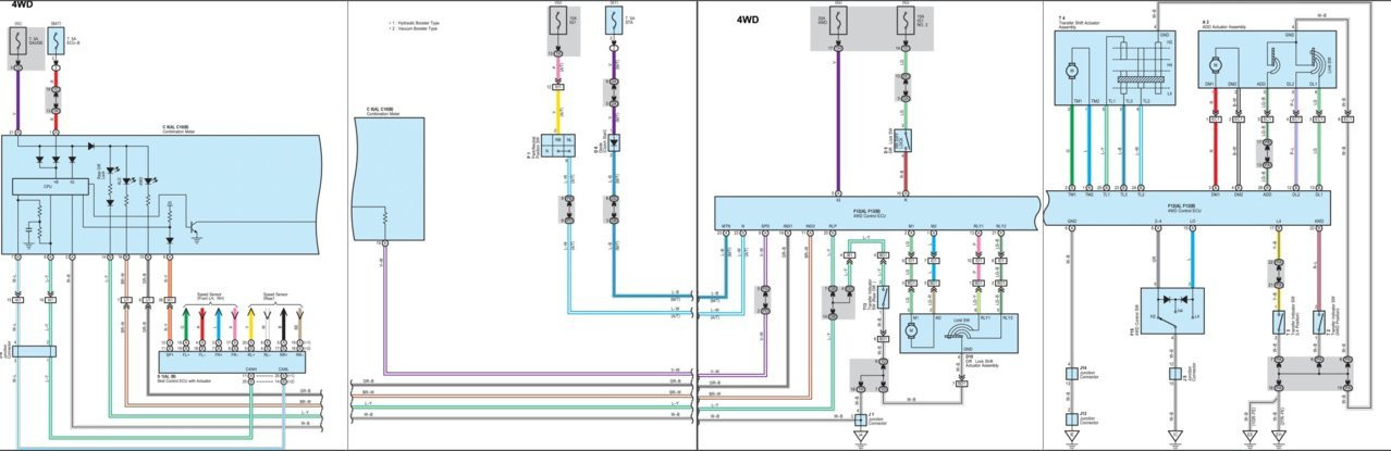
A wiring diagram is a detailed map of your vehicle’s electrical system, showing all the components and how they are connected. It can seem intimidating at first, but with a bit of practice, you can learn to read and use it effectively.
Wiring diagrams can tell you:
- Component Identification: Shows what components are in a system.
- Wiring Layout: Illustrates how components are wired.
- Current Flow: Indicates the flow of current in a system.
Key Elements to Focus On:
- Symbols: Each component (e.g., resistor, capacitor, switch) has a specific symbol. Learn to recognize these.
- Circuit Layout: Understand how circuits are arranged (series, parallel) to predict electrical behavior.
- Wire Colors: Each wire is color-coded. Use this to trace wires physically in the car.
To troubleshoot a system, we often need to refer to a wiring diagram. The information on a wiring diagram helps us understand the components, wiring, and the flow of current. Without a wiring diagram, it is very difficult to start troubleshooting.
Recall that a wiring diagram has a line and a control side. The line side of the circuit is usually powered by 240V. The control side of the circuit is usually powered by 24V.
4. The Hopscotch Method Explained
Can you explain the hopscotch method for diagnosing electrical problems, and when is it most effective?
The hopscotch method involves systematically checking voltage at each component along a circuit. It’s most effective for pinpointing where voltage drops occur, indicating a potential fault like a broken wire or faulty component.
The hopscotch method is a systematic approach to diagnosing electrical problems by following the flow of electricity in a circuit. It’s like jumping from one point to another, checking the voltage at each step to find where the electrical flow stops.
With the hopscotch method, you follow the flow of electricity in a circuit. At each component, you will take a voltage measurement with your multimeter. Recall that as voltage passes through a component, you will see a voltage drop. You will measure the voltage across each component until you find a component that receives 0V. If a component has 0V, the specific component may be faulty.
How it Works:
- Start at the Power Source: Begin at the battery or power source.
- Check Voltage: Use a multimeter to measure the voltage at each connection point or component.
- Follow the Circuit: Move along the circuit, checking voltage at each successive point.
- Identify the Drop: When you find a point with significantly lower or no voltage, you’ve located the area of the fault.
When to Use:
- No Power to a Component: When a component isn’t working, use the hopscotch method to find out where the power is being lost.
- Simple Circuits: Best for straightforward circuits where the electrical path is clear.
- Specific Component Issues: If you suspect a particular component is faulty, use this method to test it directly.
For example, imagine that your new dishwasher stops working. Instead of replacing the dishwasher, you can troubleshoot the problem.
5. Identifying Open Circuits
What are the common causes of open circuits in vehicles, and how can you effectively diagnose them?
Common causes include broken wires, corroded connections, and faulty switches. Diagnosing open circuits involves using a multimeter to check for continuity, identifying breaks in the circuit path, and ensuring all connections are secure and functional.
An open circuit is an electrical fault where the circuit is incomplete, preventing current from flowing. It’s like a broken bridge in a road, stopping traffic from passing through.
Common Causes:
- Broken Wires: Physical damage or wear and tear can cause wires to break.
- Corroded Connections: Corrosion can build up at connection points, blocking the flow of electricity.
- Faulty Switches: A switch that doesn’t close properly can create an open circuit.
- Blown Fuses: A fuse that blows due to an overload can open the circuit.
How to Diagnose:
- Visual Inspection: Check for obvious signs of damage, like broken or frayed wires.
- Continuity Test: Use a multimeter to check for continuity. Set the multimeter to the continuity setting. Insert the black connector into the COM port. The red port should be inserted into the mVΩ port. Touch the tip of your leads together. You should hear a beep sound and the display should say 0. Place one lead on one end of the wire and the other lead on the other end. If the meter beeps and displays a value close to 0, there is continuity. If it is an open circuit, your meter will display “OL”.
- Voltage Test: Check for voltage at various points in the circuit to see where the power stops.
To check for an open circuit, we will use the continuity setting on your multimeter. Start by setting your multimeter to continuity. Insert the black connector into the COM port. The red port should be inserted into the mVΩ port. Touch the tip of your leads together.You should hear a beep sound and the display should say 0.
For example, the indoor fan motor on an HVAC unit is not running. You would need to check the wiring, windings, fan relay, and other components for continuity.
6. Diagnosing Short Circuits
What are the telltale signs of a short circuit in a vehicle, and what steps should you take to locate the fault?
Telltale signs include blown fuses, burnt wires, and malfunctioning components. To locate the fault, visually inspect for damaged insulation, use a multimeter to check for continuity between the hot wire and ground, and systematically isolate circuit sections to pinpoint the short.
A short circuit occurs when electricity takes an unintended path of low resistance, causing excessive current flow. It’s like a detour on a highway that overloads a small road, leading to potential damage.
Telltale Signs:
- Blown Fuses: A fuse that repeatedly blows is a strong indicator of a short circuit.
- Burnt Wires: Overheated wires can melt or burn, indicating a short.
- Malfunctioning Components: Components that fail suddenly or behave erratically.
- Burning Smell: A distinct burning smell, especially near electrical components.
Steps to Locate the Fault:
- Visual Inspection: Look for damaged insulation, melted wires, or signs of burning.
- Continuity Test to Ground: Use a multimeter to check for continuity between the hot wire and ground. If there is continuity, a short circuit is present. Start by setting your multimeter to continuity. Insert the black connector into the COM port. The red connector should be inserted into the mVΩ port.Touch the tip of your leads together. You should hear a beep sound and the display should say 0. Place one lead on the hot terminal of the component. The other lead should be placed on the ground terminal.
- Isolate Circuit Sections: Disconnect sections of the circuit one by one to isolate the area with the short.
In the field, there is a common misunderstanding that a short circuit describes all broken components. A short circuit is a specific type of electrical fault.
7. Understanding Overamping
What does overamping signify in an electrical system, and how can you identify and prevent it?
Overamping signifies excessive current flow beyond a component’s safe limit, leading to overheating and damage. Identify overamping by checking component data sheets for maximum current ratings and using a clamp multimeter to measure current flow. Prevent it by ensuring proper circuit protection with fuses and circuit breakers.
Overamping occurs when an electrical component draws more current than it is designed to handle. It’s like trying to force too much water through a pipe, causing it to burst.
What it Signifies:
- Excessive Current Flow: The component is drawing more current than its safe limit.
- Overheating: Excessive current causes the component to overheat.
- Damage: Over time, overamping can damage or destroy the component.
How to Identify:
- Check Data Sheets: Refer to the component’s data sheet to find its maximum current rating.
- Clamp Multimeter: Use a clamp multimeter to measure the current flowing through the wire. If your meter displays a higher current than the data sheet, then the component is overamping. If a component is receiving too much current, it will heat up and be destroyed.
How to Prevent:
- Proper Circuit Protection: Use fuses and circuit breakers to protect circuits from excessive current.
- Correct Component Ratings: Ensure that components are rated to handle the current they will be subjected to.
- Regular Inspections: Check for signs of overheating or damage during routine maintenance.
To determine if a component is overamping, we will use a clamp multimeter. Recall that a clamp multimeter has a claw on top. The claw can measure the current of a wire inside the claw. Start by grabbing your clamp multimeter. Open the jaws of the clamp meter. Close the jaws of the multimeter so that the wire is in the middle of the clamp.
If a component is overamping, it will usually be damaged when you see it. For example, a blown fuse indicates that the system had too much current. You should look for the reason the system has too much current. Do not just replace the fuse.
8. The Role of Grounding
Why is proper grounding crucial in vehicle electrical systems, and how can you verify its integrity?
Proper grounding ensures a safe return path for electrical current, preventing shocks and protecting components from damage. Verify grounding integrity by checking continuity between ground points and the vehicle chassis, ensuring low resistance and secure connections.
Grounding connects electrical systems to the earth and is designed to keep you safe when touching electrical equipment. If a component is not grounded, you can be shocked when touching it.
When you are troubleshooting, always make sure that the system is grounded. If you work on an ungrounded system, you can be shocked.
Types of Grounding:
- Equipment Grounding: Connects components to non-current carrying conductors.
- System Grounding: Connects the neutral points of a conductor to the earth.
9. Testing Capacitors
How can you test capacitors to determine if they are functioning correctly in automotive circuits?
Testing capacitors involves using a multimeter set to measure capacitance (farads). Compare the measured value to the capacitor’s rating; a significant deviation indicates a faulty capacitor. Also, visually inspect for physical damage such as bulging or leaking.
Recall that an electrical fault is a system failure that prevents a component from running. A bad capacitor is one of the most common electrical faults.
Recall that a capacitor is a device used to store electrical energy in a circuit. A faulty capacitor will not store electrical energy. To test if a capacitor is faulty, we will use the farads setting on our multimeter. Recall that farads is the unit of measurement for capacitance.
Testing Steps:
- Disconnect Capacitor: Before handling a capacitor, we need to disconnect the capacitor from the system. Remove the wires from the terminals of the capacitor. Pull the capacitor out of the system.
- Discharge Capacitor: To test a capacitor, we need to discharge it. Recall that capacitors can store electrical energy even after the power to the circuit has been turned off.To discharge a capacitor, place a test resistor across the two terminals of the capacitor.
- Set Multimeter: Turn the multimeter dial to the farads setting. The black connector plugs into the COM port. The red connector plugs into the port with the capacitance symbol.
- Measure Capacitance: To measure the capacitance of a single run capacitor, we need to place one multimeter probe on each terminal.
Single Run Capacitors: If the measurement on your multimeter is within 10% of the capacitor’s rating, then the capacitor is functioning well. If the value is above or below the 10% range, then the capacitor needs to be replaced.
Dual Run Capacitors: Dual run capacitors have a different rating system than single run capacitors. A dual run capacitor may be labeled 45/5 microfarads. The first number (45) is the capacitance between HERM and COM. The second number (5) is the capacitance between FAN and COM.
10. Identifying Seized Motors
What are the symptoms of a seized motor in a vehicle, and how can you confirm the diagnosis?
Symptoms include a humming noise when power is applied, failure to start, and sluggish manual rotation. Confirm the diagnosis by checking for voltage at the motor terminals, testing the capacitor, and attempting to manually rotate the motor; resistance indicates a seized motor.
A common reason systems stop working is a problem with the motor. A seized motor is a common problem. A seized motor is a motor that is not working when it is receiving power.
Motors can fail for several reasons including:
- A bad capacitor,
- Shorted windings, and
- Open windings
Symptoms of a Seized Motor:
- Humming Noise: A seized motor will usually make a humming noise when the power is turned on. A humming noise from a motor generally means that the motor is seized.
- Failure to Start: The motor does not start when power is applied.
- Sluggish Manual Rotation: You can also manually rotate the motor wheel. If the wheel feels sluggish, the motor is seized up.
Diagnosis Confirmation Steps:
- Check for Voltage: Ensure the motor is receiving the correct voltage.
- Test Capacitor: Most motors use a run capacitor to help start the motor. If a run capacitor has gone bad, the motor may not start.
- Manual Rotation: Try to manually rotate the motor. Resistance confirms a seized motor.
Once you identify a motor is seized, there are a few things you can check. Most motors use a run capacitor to help start the motor. If a run capacitor has gone bad, the motor may not start.
11. Step-by-Step Troubleshooting Example
Can you provide a step-by-step example of troubleshooting a common electrical issue in a vehicle, such as a non-functional headlight?
- Verify Power: Use a test light to confirm power at the headlight connector.
- Check the Bulb: Inspect the bulb for damage; replace if necessary.
- Test the Switch: Use a multimeter to check continuity through the headlight switch.
- Inspect Wiring: Look for breaks or corrosion in the wiring harness.
- Check Ground: Ensure the headlight has a good ground connection.
For this example, you are an HVAC technician. You have been called out to a customer’s home. The customer explains that the unit is not heating or cooling the house.
We want to make sure that the thermostat is calling for heating or cooling. To do this, go to the thermostat in the home. Set the thermostat to a value above or below the room temperature. This should cause the unit to turn on. Check the air vents to see if warm, cool, or no air is moving into the house.
You may check if the following equipment is running:
- Indoor fan motor,
- Compressor, and
- Condenser fan motor
If no equipment is running, the thermostat may not be calling for heating or cooling. If some equipment is running, the problem is most likely not in the thermostat.
12. Advanced Diagnostic Techniques
What advanced techniques, such as using an oscilloscope or thermal imaging, can aid in complex electrical fault diagnosis?
Oscilloscopes provide detailed waveform analysis to identify intermittent or unusual electrical signals, while thermal imaging detects overheating components, indicating potential faults. These advanced tools enhance diagnostic accuracy for complex electrical issues.
To check each component, we will use the hopscotch method. Set your multimeter to measure AC voltage. Your black lead should be plugged in the COM port. Your red lead should be plugged into the mVΩ port.
- Checking the Switch: To check the fan switch in the thermostat, we will confirm that the contactor coil of the relay is receiving 24V. Place your leads on opposite ends of the relay contactor coil. Your meter reads 24V. This means that the fan switch in the thermostat is working. Next, we need to check if the relay is faulty.
- Checking the Relay: To test the indoor fan relay, we start by checking the incoming voltage to the relay. Connect your multimeter leads to the terminals at the top of the relay. Your multimeter reads 240V. The indoor fan relay is receiving the correct amount of power. Next, we will check if we have 240V on the load side of the relay. Place your leads on the outgoing terminals of the relay. The multimeter reads 240V. The problem is not with the indoor fan relay.
- Checking the Capacitor: Next, we need to test the run capacitor. Set your multimeter to measure capacitance. Place your black lead on the COM terminal of the capacitor. Your red lead should go on the FAN terminal. Your multimeter reads 4.9µF. The capacitor is working. Next, you need to measure from HERM to COM. Place your black lead on the COM terminal of the capacitor. Your red lead should go on the HERM terminal. Your multimeter reads 44.2µF. The capacitor is working.
13. Safety Precautions
What safety precautions should you observe when troubleshooting electrical faults in vehicles?
Always disconnect the battery before working on electrical systems, use insulated tools, wear safety glasses, and avoid working in wet conditions. Additionally, be aware of airbag systems and high-voltage components in hybrid or electric vehicles.
Always disconnect the battery before working on electrical systems.
- Use insulated tools
- Wear safety glasses
- Avoid working in wet conditions
- Be aware of airbag systems
- Be aware of high-voltage components in hybrid or electric vehicles
14. Utilizing CARDIAGTECH.NET for Solutions
How can CARDIAGTECH.NET assist in resolving electrical faults in vehicles?
CARDIAGTECH.NET offers a range of diagnostic tools, wiring diagrams, and expert advice to help identify and fix electrical faults efficiently. Our products and resources are designed to empower both professionals and DIY enthusiasts with the knowledge and equipment needed for successful troubleshooting.
CARDIAGTECH.NET is your trusted partner in resolving electrical faults in vehicles. Here’s how we can assist you:
- Diagnostic Tools: We offer a wide range of high-quality diagnostic tools, including multimeters, circuit testers, and oscilloscopes, to accurately identify electrical issues.
- Wiring Diagrams: Access comprehensive wiring diagrams for various vehicle makes and models, helping you trace circuits and pinpoint faults.
- Expert Advice: Our team of experienced technicians provides expert advice and support to guide you through the troubleshooting process.
- Training Resources: We offer training materials and tutorials to enhance your knowledge and skills in electrical troubleshooting.
Visit CARDIAGTECH.NET today to explore our extensive catalog of automotive diagnostic tools and resources. Enhance your troubleshooting capabilities and ensure your vehicle’s electrical system is in top condition with CARDIAGTECH.NET.
15. Proactive Maintenance
What proactive maintenance steps can prevent electrical faults in vehicles?
Regularly inspect wiring for damage or corrosion, ensure connections are secure, replace worn-out components, and keep the battery terminals clean. These steps help maintain the integrity of the electrical system and prevent potential faults.
CARDIAGTECH.NET is dedicated to providing the best tools and resources for automotive electrical troubleshooting. Our products are designed to meet the needs of both professional technicians and DIY enthusiasts, ensuring accurate and efficient diagnostics.
To further assist you, we offer a range of support services, including detailed product guides, troubleshooting tips, and expert advice. At CARDIAGTECH.NET, we are committed to helping you keep your vehicle’s electrical system in top condition, ensuring safety and reliability on the road.
Electrical faults can be frustrating, but with the right tools and knowledge, you can diagnose and fix them effectively. Stay proactive, use high-quality equipment from CARDIAGTECH.NET, and keep your vehicle running smoothly.
Don’t let electrical issues keep you off the road. Equip yourself with the best tools and knowledge from CARDIAGTECH.NET, and take control of your vehicle’s electrical health.
FAQ: Electrical Faults in Vehicles
1. What is an electrical fault?
An electrical fault is a malfunction within an electrical circuit that disrupts normal operation. It can manifest as a short circuit, open circuit, or overamping condition.
2. What are the most common types of electrical faults in vehicles?
The most common types include short circuits, open circuits, overamping, and ground faults.
3. How can I identify a short circuit in my car?
Signs of a short circuit include blown fuses, burnt wires, malfunctioning components, and a burning smell.
4. What is an open circuit, and how is it diagnosed?
An open circuit is an incomplete circuit that prevents current flow. It is diagnosed using a multimeter to check for continuity.
5. What does overamping mean, and how can I prevent it?
Overamping is excessive current flow beyond a component’s safe limit. Prevent it by ensuring proper circuit protection with fuses and circuit breakers.
6. Why is grounding important in vehicle electrical systems?
Proper grounding ensures a safe return path for electrical current, preventing shocks and protecting components from damage.
7. How do I test a capacitor in my car’s electrical system?
Test capacitors using a multimeter set to measure capacitance (farads). Compare the measured value to the capacitor’s rating; a significant deviation indicates a faulty capacitor.
8. What are the symptoms of a seized motor in a vehicle?
Symptoms include a humming noise when power is applied, failure to start, and sluggish manual rotation.
9. What tools are essential for diagnosing electrical faults in vehicles?
Essential tools include a multimeter, test light, wiring diagrams, wire strippers, and crimpers.
10. How can CARDIAGTECH.NET help me resolve electrical faults in my vehicle?
CARDIAGTECH.NET offers a range of diagnostic tools, wiring diagrams, and expert advice to help identify and fix electrical faults efficiently.
Ready to tackle those electrical gremlins in your car? Contact CARDIAGTECH.NET now for expert advice and the best diagnostic tools on the market. Reach us at 276 Reock St, City of Orange, NJ 07050, United States, or give us a call/WhatsApp at +1 (641) 206-8880. Check out our website at CARDIAGTECH.NET and let us help you keep your ride running smoothly. Get in touch today and drive with confidence