**What Are The Basic Types of Electrical Circuits? A Comprehensive Guide**
What are the basic types of electrical circuits, such as series and parallel? This in-depth guide from CARDIAGTECH.NET explores fundamental electrical circuit types, their applications, and troubleshooting tips, ensuring efficient and safe automotive repairs. By understanding these circuits and utilizing the right diagnostic tools, you can enhance your repair accuracy and service quality, contributing to increased customer satisfaction and business growth. Get ready to enhance your understanding with terms like circuit schematics, wiring diagrams, and automotive electrical systems.
1. Understanding Electrical Circuits: An Overview
What exactly is an electrical circuit, and why is it important in automotive repair? An electrical circuit is a closed path that allows electric current to flow, powering various components in a vehicle, as defined by basic electrical theory. These circuits are essential for everything from lighting systems to engine control units, according to the University of Michigan’s Electrical Engineering Department. Understanding how these circuits function is critical for diagnosing and fixing electrical issues, enabling technicians to efficiently restore vehicle functionality.
1.1 What is an Electric Circuit?
An electric circuit is a closed loop network that provides a return path for the flow of current. As mentioned in “Practical Electronics for Inventors” by Paul Scherz and Simon Monk, an electrical circuit is a closed conducting path in which current can flow. It’s also known as an electrical network.
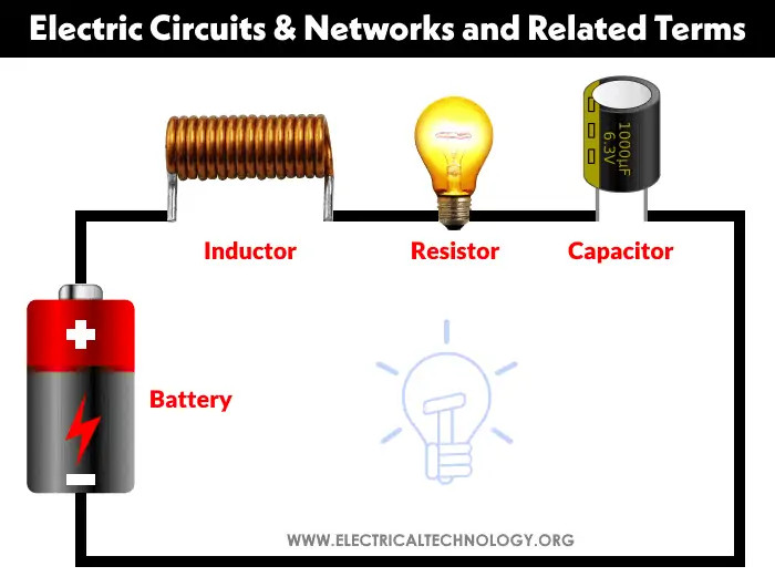
An electrical circuit combines various active and passive components such as resistors, capacitors, inductors, diodes, and transistors, forming an electrical network. In a closed-loop circuit, the electric current flows from the source (e.g., battery) through conducting material (wires and cables) to the load (e.g., light bulb) and returns to the source.
1.2 What is an Electronic Circuit?
An electronic circuit is a specific type of electric circuit that contains electronic components such as diodes, transistors, resistors, and capacitors. The key difference, as noted in “Electronic Devices and Circuit Theory” by Robert Boylestad and Louis Nashelsky, is that an electronic circuit must include at least one active component, distinguishing it from a basic electrical circuit. This allows for more complex functions such as signal amplification and processing.
1.3 What is an Electrical Network?
An electrical network refers to a combination of interconnected electrical elements and components arranged in either simple or complex configurations. The “Handbook of Electric Power Calculations” by H. Wayne Beaty defines it as a broader term often associated with complex arrangements that require network theorems for analysis.
1.4 Complex Networks
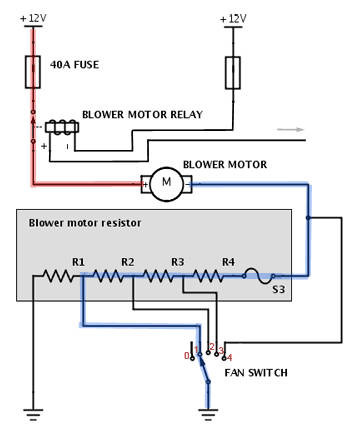
A complex network contains numerous electrical elements like resistors, capacitors, inductors, and both AC and DC current and voltage sources in complex configurations. These networks, as explained in “Basic Engineering Circuit Analysis” by J. David Irwin and Robert M. Nelms, are not easily solved using simple Ohm’s Law or Kirchhoff’s Laws. Instead, they require advanced techniques such as network theorems, including Norton’s theorem, Thevenin’s theorem, and superposition theorem.
Complex Electrical Network
2. Basic Types of Electrical Circuits: Essential Knowledge
What are the main types of electrical circuits? The most fundamental types of electrical circuits include open, closed, short, series, and parallel circuits. These configurations dictate how components are connected and how current flows through the circuit, as detailed in “Electricity and Electronics Fundamentals” by Dale R. Patrick and Stephen W. Fardo. Understanding these basic types is crucial for diagnosing and resolving electrical issues effectively.
2.1 Open Circuit
What happens in an open circuit? An open circuit occurs when there is no complete path for current to flow, such as when a switch is open or a wire is broken. As described in “Understanding Electricity and Electronics” by Michael B. Green, in an open circuit, voltage tends to the EMF (of the generating source), and no current flows at all.
Example of an open circuit: A circuit with an open switch or a blown fuse connected to a light bulb. The bulb won’t light because the circuit is incomplete, and no current is flowing.
2.2 Closed Circuit
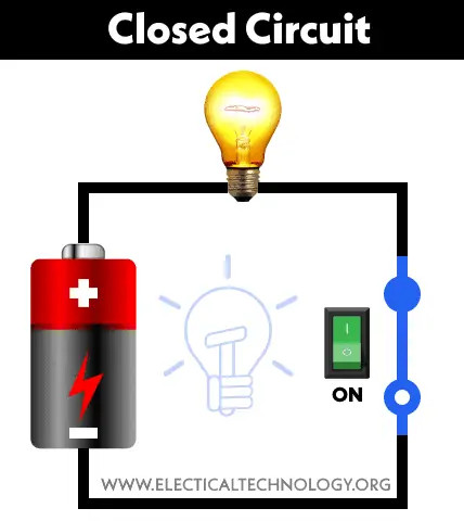
What defines a closed circuit? A closed circuit has a complete path for current to flow, allowing electrical components to function. As highlighted in “Electrical Engineering: Principles and Applications” by Allan R. Hambley, this is the basic requirement for any electrical device to operate.
 Closed Electrical Circuit
Example of a closed circuit: A circuit with a closed switch where a light bulb is connected to a battery. The bulb lights up because current flows through the filament due to the completed circuit.
2.3 Short Circuit
What is a short circuit, and why is it dangerous? A short circuit occurs when current bypasses the intended load and flows along a low-resistance path, leading to a sudden increase in current. According to “National Electrical Code Handbook” by Frederic P. Hartwell, this can cause overheating, damage to components, and even fires if not properly protected.
Example of a short circuit: When a phase or line wire touches the neutral wire without a load between them. The fuse will blow or the circuit breaker will trip. Without proper protection, a short circuit can damage appliances or cause serious injury.
2.4 Series Circuit
How does a series circuit work? In a series circuit, all components are connected along a single path, meaning the same current flows through each component. As “Introductory Circuit Analysis” by Robert L. Boylestad explains, the total resistance in a series circuit is the sum of individual resistances.
 Series Electrical Circuit
2.5 Parallel Circuit
How does a parallel circuit differ from a series circuit? In a parallel circuit, components are connected along multiple paths, so the voltage across each component is the same, but the current can divide among the different paths. As illustrated in “Fundamentals of Electric Circuits” by Charles K. Alexander and Matthew N. O. Sadiku, the reciprocal of the total resistance in a parallel circuit is the sum of the reciprocals of the individual resistances.
2.6 Series-Parallel Circuit
What is a series-parallel circuit? A series-parallel circuit combines elements of both series and parallel connections, offering a mix of current and voltage characteristics. In “Delmar’s Standard Textbook of Electricity” by Stephen L. Herman, it’s explained that these circuits require careful analysis to determine the current and voltage distribution across each component.
2.7 Star-Delta Circuit
What are star and delta circuits used for? Star (Y) and delta (Δ) circuits are three-phase configurations used to connect components in a balanced or unbalanced manner. “Electrical Power Systems” by C. L. Wadhwa states that these configurations are commonly used in power distribution networks and motor connections.
2.8 AC Circuit
What is an AC circuit, and how is it used? An AC (alternating current) circuit uses a power source that periodically reverses direction, typically used in household and industrial applications. As noted in “Alternating Current Machines” by A. F. Puchstein, T. C. Lloyd, and A. G. Conrad, AC circuits are essential for power transmission and distribution.
2.9 DC Circuit
What is a DC circuit, and where is it typically found? A DC (direct current) circuit uses a power source that flows in one direction, commonly found in batteries and electronic devices. In “Direct Current Fundamentals” by Stephen L. Herman, it is detailed that DC circuits provide a stable and constant power supply.
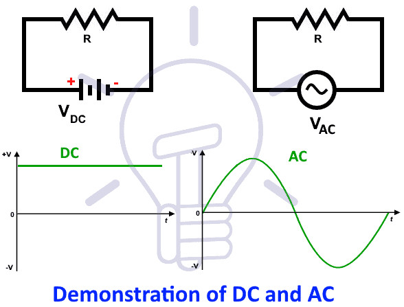 AC and DC Power Demonstration
2.10 Single Phase Circuits
What are single-phase circuits used for? Single-phase AC circuits use two wires (phase and neutral) to deliver power in residential and light commercial applications. As explained in “Electric Power Distribution Engineering” by Turan Gonen, these circuits are suitable for lower power requirements where simplicity and cost-effectiveness are important.
2.11 Polyphase Circuits
What are polyphase circuits, and where are they used? Polyphase AC circuits, typically three-phase, use multiple voltage waveforms with phase differences to deliver more power efficiently, used in industrial applications. As highlighted in “Power System Analysis and Design” by J. Duncan Glover, Mulukutla S. Sarma, and Thomas J. Overbye, three-phase systems are ideal for high-power applications like motors and generators.
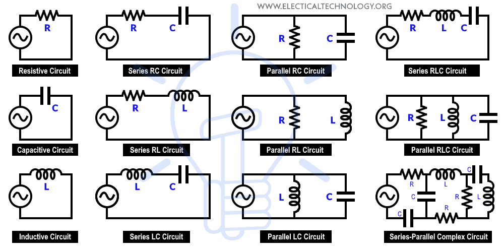
2.12 Resistive Circuit
What is a resistive circuit? A circuit that contains only resistors, consuming electrical energy and dissipating it as heat. “Practical Electronics for Inventors” by Paul Scherz describes resistive circuits as the simplest form of circuit, used for voltage division, current limiting, and heat generation.
2.13 Inductive Circuit
What is an inductive circuit? A circuit that contains inductors, storing energy in a magnetic field when current flows through it. As noted in “Electromagnetic Fields and Waves” by Paul Lorrain and Dale Corson, inductive circuits are used in filters, energy storage, and electromagnetic devices.
2.14 Capacitive Circuit
What is a capacitive circuit? A circuit that contains capacitors, storing energy in an electric field. As explained in “Microelectronics” by Jacob Millman and Arvin Grabel, capacitive circuits are used in filters, timing circuits, and energy storage.
2.15 Resistive, Inductive (RL Circuit)
What is an RL circuit? A circuit that contains both resistors and inductors, exhibiting a combination of resistive and inductive properties. “Engineering Circuit Analysis” by William Hayt and Jack Kemmerly explains that RL circuits are used in filters, impedance matching, and power supplies.
2.16 Resistive, Capacitive (RC Circuit)
What is an RC circuit? A circuit that contains both resistors and capacitors, exhibiting both resistive and capacitive properties. In “Electronic Devices and Circuit Theory” by Robert Boylestad and Louis Nashelsky, it’s noted that RC circuits are used in filters, timing circuits, and signal coupling.
2.17 Capacitive, Inductive (LC Circuits)
What is an LC circuit? A circuit that contains both inductors and capacitors, oscillating energy between the inductor’s magnetic field and the capacitor’s electric field. “Radio Engineering” by Frederick Emmons Terman describes LC circuits as being used in oscillators, resonant circuits, and filters.
2.18 Resistive, Inductive, Capacitive (RLC Circuit)
What is an RLC circuit? A circuit that contains resistors, inductors, and capacitors, combining resistive, inductive, and capacitive properties. “Circuit Analysis and Design” by Fawwaz Ulaby, Michel Maharbiz, and Cynthia Furse explains that RLC circuits are used in filters, oscillators, and impedance matching.
2.19 Linear Circuit
What defines a linear circuit? A linear circuit is one in which the relationship between voltage and current is linear. According to “Linear and Nonlinear Circuits” by Chua, Desoer, and Kuh, the circuit parameters (resistance, inductance, and capacitance) are constant and do not change with voltage or current.
2.20 Non-Linear Circuit
What is a non-linear circuit? A non-linear circuit is one in which the relationship between voltage and current is non-linear. As explained in “Nonlinear Circuits Handbook” by George E. Totten, the circuit parameters change with voltage or current, making the analysis more complex.
2.21 Unilateral Circuits
What are unilateral circuits? Unilateral circuits allow current to flow in only one direction. “Semiconductor Physics and Devices” by Donald A. Neamen notes that diodes and rectifiers are examples of unilateral circuits, as they only allow current to flow in one direction.
2.22 Bi-Lateral Circuits
What are bi-lateral circuits? Bi-lateral circuits allow current to flow in both directions. In “Network Analysis” by M.E. Van Valkenburg, it’s stated that transmission lines are examples of bi-lateral circuits because their properties remain constant regardless of the direction of current flow.
2.23 Active Circuit
What defines an active circuit? An active circuit contains one or more sources of EMF (electromotive force). “Operational Amplifiers and Linear Integrated Circuits” by Robert F. Coughlin and Frederick F. Driscoll explains that active circuits can provide power gain and are used in amplifiers and oscillators.
2.24 Passive Circuit
What is a passive circuit? A passive circuit does not contain any EMF sources. “Passive Circuit Components” by Richard Y. York states that passive circuits consist only of passive components like resistors, capacitors, and inductors.
3. Circuit Parameters, Constants, and Related Terms: Key Concepts
What are the key parameters and terms used in electrical circuits? Understanding circuit parameters such as resistance, capacitance, inductance, and frequency is crucial for analyzing and troubleshooting electrical circuits. These parameters, as noted in “Electrical Engineering Principles and Applications” by Allan R. Hambley, can be either lumped or distributed.
3.1 Node
What is a node in an electrical circuit? A node is a point or junction where two or more circuit elements meet. “Microelectronics” by Jacob Millman and Arvin Grabel defines a node as a common connection point for multiple components in a circuit.
3.2 Branch
What is a branch in an electrical circuit? A branch is a section of a circuit located between two junctions, containing one or more elements connected in series. In “Circuit Analysis: Theory and Practice” by Allan H. Robbins and Wilhelm C. Miller, a branch is described as a single path connecting two nodes in a circuit.
3.3 Loop
What is a loop in an electrical circuit? A loop is a closed path in a circuit where more than two meshes can occur. “Basic Engineering Circuit Analysis” by J. David Irwin and Robert M. Nelms explains that a loop is any closed path that allows you to start at a point and return to the same point without leaving the circuit.
3.4 Mesh
What is a mesh in an electrical circuit? A mesh is a closed loop that contains no other loops within it. “Introductory Circuit Analysis” by Robert L. Boylestad describes a mesh as the most basic form of a loop, containing no internal loops.
 Circuit Nodes, Branches, Loops, and Meshes
3.5 Impedance
How does impedance affect AC circuits? Impedance is the total opposition to current flow in an AC circuit, including both resistance and reactance (capacitive and inductive). “Understanding AC Circuits” by Stanley explains that impedance is crucial for analyzing AC circuits, affecting voltage and current relationships.
3.6 Reactance
What is reactance in AC circuits? Reactance is the opposition to current flow caused by capacitors and inductors in AC circuits. As mentioned in “Electronics Fundamentals: Circuits, Devices & Applications” by Thomas L. Floyd, reactance varies with frequency, affecting the behavior of AC circuits.
3.7 Admittance
What is admittance? Admittance is the measure of how easily a circuit allows current to flow, the inverse of impedance. “Electrical Circuit Theory and Technology” by John Bird notes that admittance is particularly useful in parallel AC circuits.
4. Troubleshooting Electrical Circuits: Techniques and Tools
What are the best practices for troubleshooting electrical circuits? Effective troubleshooting involves systematic testing, accurate diagnostics, and the use of appropriate tools such as multimeters and circuit testers. CARDIAGTECH.NET offers a range of diagnostic tools designed to help technicians quickly identify and resolve electrical issues, enhancing repair efficiency and accuracy.
4.1 Essential Tools for Circuit Testing
What tools are essential for testing electrical circuits? A multimeter is essential for measuring voltage, current, and resistance. According to “Automotive Electrical Handbook” by Joseph Miles, other key tools include circuit testers, oscilloscopes, and diagnostic scanners for complex systems.
CARDIAGTECH.NET provides high-quality multimeters that are accurate and durable, ensuring reliable measurements for automotive diagnostics. Investing in quality tools from CARDIAGTECH.NET ensures technicians can accurately diagnose and repair electrical issues, minimizing errors and maximizing efficiency.
4.2 Step-by-Step Troubleshooting Guide
How do you systematically troubleshoot an electrical circuit?
- Visual Inspection: Check for obvious signs of damage like broken wires or burnt components.
- Continuity Testing: Use a multimeter to check for breaks in the circuit.
- Voltage Testing: Measure voltage at different points to identify drops or incorrect levels.
- Component Testing: Test individual components like fuses, relays, and sensors.
- Consult Wiring Diagrams: Use wiring diagrams to understand the circuit layout.
By following this systematic approach, technicians can efficiently diagnose and repair electrical faults, reducing downtime and improving customer satisfaction. CARDIAGTECH.NET supports this process by offering comprehensive diagnostic tools and resources.
4.3 Common Electrical Faults and Solutions
What are some common electrical faults and their solutions? Common faults include open circuits, short circuits, ground faults, and component failures. Solutions involve repairing or replacing damaged components, fixing wiring issues, and ensuring proper grounding.
By understanding these common issues and their solutions, technicians can quickly resolve electrical problems, enhancing their productivity and service quality. CARDIAGTECH.NET provides the tools and knowledge needed to tackle these challenges effectively.
4.4 Safety Precautions When Working with Electrical Circuits
What safety precautions should be taken when working with electrical circuits? Always disconnect the power source before working on a circuit, use insulated tools, and wear appropriate personal protective equipment (PPE). As emphasized in “Electrical Safety Handbook” by John Cadick, Mary Capelli-Schellpfeffer, and Dennis K. Neitzel, safety is paramount when working with electricity.
5. Advanced Circuit Analysis Techniques: Enhancing Your Skills
How can you enhance your circuit analysis skills? Mastering advanced techniques like network theorems, such as Thevenin’s and Norton’s theorems, can significantly improve your ability to analyze complex circuits. In addition, finite element analysis provides tools for simulating and studying the distribution of physical quantities in circuits. By incorporating these advanced methods, as highlighted in “Advanced Circuit Analysis and Design” by Del Toro, technicians can tackle intricate electrical problems with greater precision and efficiency.
5.1 Network Theorems: Thevenin’s and Norton’s
How can Thevenin’s and Norton’s theorems simplify circuit analysis? Thevenin’s theorem simplifies a complex circuit to an equivalent voltage source and series resistance, while Norton’s theorem simplifies it to an equivalent current source and parallel resistance. “Engineering Circuit Analysis” by William Hayt and Jack Kemmerly explains that these theorems are invaluable for analyzing complex circuits, reducing the complexity and making calculations easier.
5.2 Superposition Theorem
How does the superposition theorem aid in circuit analysis? The superposition theorem analyzes a linear circuit by considering the effect of each independent source separately and then summing the results. As noted in “Linear Circuit Analysis” by Raymond A. DeCarlo and Pen-Min Lin, this theorem is particularly useful when dealing with multiple voltage or current sources.
5.3 Mesh and Nodal Analysis
What are mesh and nodal analysis techniques? Mesh analysis uses Kirchhoff’s Voltage Law (KVL) to find the currents in a circuit, while nodal analysis uses Kirchhoff’s Current Law (KCL) to find the voltages. “Circuit Analysis: Theory and Practice” by Allan H. Robbins and Wilhelm C. Miller explains that these methods provide systematic approaches to solving complex circuits.
5.4 Transient Analysis
How is transient analysis used in circuits? Transient analysis examines the behavior of circuits over time as they respond to changes in voltage or current. “Fundamentals of Electric Circuits” by Charles K. Alexander and Matthew N. O. Sadiku state that this type of analysis is essential for understanding how circuits behave during switching and other dynamic conditions.
5.5 Frequency Domain Analysis
What is frequency domain analysis? Frequency domain analysis examines the behavior of circuits at different frequencies, using techniques like Bode plots and Fourier analysis. “Signals and Systems” by Alan V. Oppenheim and Alan S. Willsky explain that this analysis is crucial for designing filters and understanding how circuits respond to different frequency components.
6. Importance of Accurate Wiring Diagrams and Schematics
How important are wiring diagrams and schematics in automotive repair? Accurate wiring diagrams and schematics are crucial for understanding circuit layouts and troubleshooting electrical problems. These diagrams provide a detailed roadmap of the circuit, enabling technicians to quickly identify components and trace wiring paths. CARDIAGTECH.NET emphasizes the use of up-to-date and accurate diagrams to ensure effective and efficient diagnostics.
6.1 Understanding Wiring Diagrams
How do you read and interpret wiring diagrams? Wiring diagrams use symbols to represent components and lines to represent wires, showing how they are connected. Key elements include identifying components, tracing circuits, and understanding color codes.
6.2 Benefits of Using Schematics
What are the benefits of using schematics in circuit analysis? Schematics provide a simplified representation of a circuit, focusing on the functional relationships between components. This makes it easier to understand the circuit’s operation and troubleshoot issues.
6.3 Accessing Reliable Wiring Diagrams
Where can you find reliable wiring diagrams and schematics? Reliable sources include manufacturer service manuals, online databases, and professional diagnostic software. CARDIAGTECH.NET recommends using official service manuals and reputable online resources to ensure accuracy.
7. Enhancing Efficiency with Advanced Diagnostic Tools from CARDIAGTECH.NET
What tools does CARDIAGTECH.NET offer to enhance repair efficiency? CARDIAGTECH.NET provides a range of advanced diagnostic tools designed to streamline the troubleshooting process and improve repair accuracy. These tools include high-quality multimeters, circuit testers, and diagnostic scanners that offer comprehensive circuit analysis capabilities. By investing in these tools, repair shops can enhance their efficiency, reduce downtime, and improve customer satisfaction.
7.1 High-Quality Multimeters
How do high-quality multimeters improve diagnostic accuracy? High-quality multimeters offer precise measurements of voltage, current, and resistance, enabling technicians to accurately diagnose electrical issues. CARDIAGTECH.NET provides multimeters that are durable, reliable, and easy to use.
7.2 Advanced Circuit Testers
What are the benefits of using advanced circuit testers? Advanced circuit testers can quickly identify open circuits, short circuits, and other wiring problems, saving time and improving diagnostic accuracy. CARDIAGTECH.NET offers a variety of circuit testers designed for automotive applications.
7.3 Diagnostic Scanners
How do diagnostic scanners aid in circuit analysis? Diagnostic scanners can access vehicle computer systems to read fault codes, monitor sensor data, and perform circuit tests. CARDIAGTECH.NET provides diagnostic scanners that are compatible with a wide range of vehicle makes and models.
8. Real-World Applications: Case Studies in Automotive Repair
How are these circuit concepts applied in real-world automotive repair scenarios? Understanding electrical circuit types and troubleshooting techniques is essential for resolving a wide range of automotive issues, from lighting problems to complex engine control system failures. By applying the knowledge gained from this guide and using the right diagnostic tools from CARDIAGTECH.NET, technicians can efficiently diagnose and repair electrical faults, improving their service quality and customer satisfaction.
8.1 Case Study 1: Diagnosing a Faulty Lighting System
How do you diagnose a faulty lighting system using circuit knowledge?
- Problem: Headlights not working.
- Tools: Multimeter, wiring diagram.
- Steps:
- Check the fuse for the headlight circuit.
- Test the voltage at the headlight connector.
- Check the continuity of the wiring between the switch and the headlights.
8.2 Case Study 2: Repairing an Engine Control System
How do you repair an engine control system using advanced diagnostic techniques?
- Problem: Engine misfire due to a faulty sensor.
- Tools: Diagnostic scanner, multimeter.
- Steps:
- Use the diagnostic scanner to read fault codes.
- Test the sensor circuit for voltage and continuity.
- Replace the faulty sensor and clear the fault codes.
8.3 Case Study 3: Troubleshooting a Short Circuit
How do you troubleshoot a short circuit in a vehicle?
- Problem: Fuse keeps blowing.
- Tools: Circuit tester, wiring diagram.
- Steps:
- Identify the circuit that the fuse protects.
- Inspect the wiring for signs of damage or chafing.
- Use the circuit tester to isolate the short circuit.
9. Staying Updated with the Latest Automotive Electrical Technology
How can automotive technicians stay updated with the latest electrical technology? The automotive industry is constantly evolving, with new technologies and systems being introduced regularly. Technicians need to stay updated through continuous education, training programs, and industry resources. CARDIAGTECH.NET supports this by providing access to the latest diagnostic tools, training materials, and technical support.
9.1 Industry Training Programs
What are the best industry training programs for automotive electrical systems? Programs offered by manufacturers, trade schools, and professional organizations like ASE (Automotive Service Excellence) provide valuable training and certification. CARDIAGTECH.NET recommends investing in these programs to enhance your skills and knowledge.
9.2 Online Resources and Forums
What online resources and forums are available for automotive technicians? Online forums, technical websites, and social media groups provide platforms for technicians to share knowledge, ask questions, and stay updated on industry trends. CARDIAGTECH.NET encourages technicians to participate in these online communities.
9.3 Trade Shows and Conferences
Why are trade shows and conferences important for professional development? Trade shows and conferences provide opportunities to see the latest tools and technologies, attend workshops, and network with industry professionals. CARDIAGTECH.NET encourages technicians to attend these events to stay ahead of the curve.
10. Future Trends in Automotive Electrical Systems
What are the future trends in automotive electrical systems? The future of automotive electrical systems is driven by advancements in electric vehicles, autonomous driving, and connected car technologies. These trends include higher voltage systems, advanced sensor technologies, and sophisticated control algorithms.
10.1 Electric Vehicles (EVs)
How are EVs changing automotive electrical systems? Electric vehicles use high-voltage electrical systems to power the motor and other components, requiring specialized diagnostic and repair techniques. CARDIAGTECH.NET provides tools and training for working with EV electrical systems.
10.2 Autonomous Driving Systems
How do autonomous driving systems impact electrical systems? Autonomous driving systems rely on a network of sensors, computers, and actuators, requiring robust and reliable electrical systems. CARDIAGTECH.NET offers diagnostic solutions for these complex systems.
10.3 Connected Car Technologies
What are the implications of connected car technologies for electrical systems? Connected car technologies integrate vehicles with the internet, enabling features like remote diagnostics, over-the-air updates, and data collection. CARDIAGTECH.NET provides tools for diagnosing and repairing these connected systems.
11. Call to Action: Upgrade Your Repair Capabilities with CARDIAGTECH.NET
Are you facing challenges with complex automotive electrical repairs? Do you struggle with time-consuming diagnostics or inaccurate results? CARDIAGTECH.NET understands the difficulties technicians face in today’s fast-paced automotive industry. Our range of high-quality diagnostic tools and equipment is designed to enhance your efficiency, accuracy, and overall service quality.
Don’t let electrical issues slow you down. Contact CARDIAGTECH.NET today to learn how our advanced tools can transform your repair capabilities. Visit our website at CARDIAGTECH.NET or reach out to us via WhatsApp at +1 (641) 206-8880 for a personalized consultation. Our experts are ready to help you select the perfect tools to meet your specific needs and elevate your service offerings.
Take the next step in automotive repair excellence with CARDIAGTECH.NET. Contact us now and experience the difference that quality tools and expertise can make. Located at 276 Reock St, City of Orange, NJ 07050, United States, we are committed to providing you with the best solutions for your automotive repair needs. Don’t wait—transform your shop into a high-efficiency, high-profit center with CARDIAGTECH.NET today. Invest in your success and see the results in satisfied customers and increased revenue.
Frequently Asked Questions (FAQ)
Q1: What are the basic types of electrical circuits?
The basic types of electrical circuits are open, closed, short, series, and parallel circuits. These configurations determine how components are connected and how current flows.
Q2: What is the difference between a series and parallel circuit?
In a series circuit, components are connected along a single path, so the same current flows through each component. In a parallel circuit, components are connected along multiple paths, so the voltage across each component is the same, but the current can divide among the different paths.
Q3: What is a short circuit, and why is it dangerous?
A short circuit occurs when current bypasses the intended load and flows along a low-resistance path, leading to a sudden increase in current. This can cause overheating, damage to components, and even fires if not properly protected.
Q4: What tools are essential for testing electrical circuits?
Essential tools include a multimeter, circuit tester, oscilloscope, and diagnostic scanner. These tools help measure voltage, current, resistance, and diagnose complex systems. CARDIAGTECH.NET offers high-quality options for each of these tools.
Q5: How do you systematically troubleshoot an electrical circuit?
- Visual Inspection: Check for obvious signs of damage.
- Continuity Testing: Use a multimeter to check for breaks in the circuit.
- Voltage Testing: Measure voltage at different points.
- Component Testing: Test individual components.
- Consult Wiring Diagrams: Use wiring diagrams to understand the circuit layout.
Q6: What safety precautions should be taken when working with electrical circuits?
Always disconnect the power source, use insulated tools, and wear appropriate personal protective equipment (PPE).
Q7: How can Thevenin’s and Norton’s theorems simplify circuit analysis?
Thevenin’s theorem simplifies a complex circuit to an equivalent voltage source and series resistance, while Norton’s theorem simplifies it to an equivalent current source and parallel resistance.
Q8: Why are wiring diagrams and schematics important in automotive repair?
Accurate wiring diagrams and schematics are crucial for understanding circuit layouts and troubleshooting electrical problems. They provide a detailed roadmap of the circuit, enabling technicians to quickly identify components and trace wiring paths.
Q9: How can automotive technicians stay updated with the latest electrical technology?
Stay updated through continuous education, training programs, industry resources, online resources, and trade shows. CARDIAGTECH.NET supports this by providing access to the latest diagnostic tools, training materials, and technical support.
Q10: What are some future trends in automotive electrical systems?
Future trends include electric vehicles (EVs), autonomous driving systems, and connected car technologies. These trends require higher voltage systems, advanced sensor technologies, and sophisticated control algorithms.