P0715 Mercedes Code: Symptoms, Causes, and Solutions
P0715 Mercedes code indicates a malfunction in the Turbine/Input Shaft Speed Sensor Circuit. Addressing it promptly is crucial to prevent transmission problems. CARDIAGTECH.NET offers top-notch diagnostic tools to accurately identify and resolve this issue, enhancing your vehicle’s performance. Ignoring it can lead to poor shift quality, reduced fuel economy, and potential transmission damage. Let’s explore how to tackle this effectively with expert insights and solutions from CARDIAGTECH.NET.
1. What Does the P0715 Mercedes Code Mean?
The P0715 Mercedes code signifies an issue within the Turbine/Input Shaft Speed Sensor “A” circuit. This sensor is crucial for monitoring the input speed of your transmission. This diagnostic trouble code (DTC) signals that the transmission control module (TCM) is receiving an irregular signal from the input shaft speed sensor. It is essential for the transmission to function correctly, impacting shift timing and overall performance.
1.1. Symptoms of a P0715 Code
When the P0715 code appears in your Mercedes, several symptoms may arise, potentially impacting the driving experience and the vehicle’s overall performance. Recognizing these signs early can lead to quicker diagnosis and repair, preventing more extensive damage. Here are some common symptoms associated with the P0715 code:
- Erratic Shifting: The transmission may shift inappropriately, either too early or too late, leading to jerky movements and an uncomfortable ride.
- Harsh Shifting: Gear changes might feel rough or abrupt, indicating the transmission is not engaging smoothly.
- Transmission Slipping: The engine RPMs may increase without a corresponding increase in vehicle speed, suggesting the transmission is not properly engaging the gears.
- Stalling: In some cases, the vehicle may stall, particularly when coming to a stop, as the transmission struggles to disengage.
- Check Engine Light: The most obvious symptom is the illumination of the check engine light on the dashboard, signaling that a fault has been detected by the vehicle’s computer.
- Reduced Fuel Economy: The vehicle’s fuel efficiency may decrease as the transmission operates inefficiently due to incorrect gear selection and slippage.
- Limp Mode: The transmission might enter a “limp mode,” restricting the vehicle to a single gear to prevent further damage, significantly limiting speed and performance.
These symptoms can vary in severity, but any indication of transmission issues should be addressed promptly to avoid costly repairs.
1.2. Common Causes of the P0715 Code
Several factors can trigger the P0715 code in your Mercedes. Understanding these potential causes can help in accurately diagnosing and resolving the problem. Here are the common culprits behind the P0715 code:
- Faulty Input Shaft Speed Sensor: The sensor itself might be defective, providing inaccurate readings to the TCM.
- Wiring Issues: Damaged, corroded, or loose wiring connected to the input shaft speed sensor can disrupt the signal.
- Connector Problems: Corroded or loose connectors can prevent the sensor from communicating correctly with the TCM.
- Contaminated Transmission Fluid: Dirty or degraded transmission fluid can interfere with the sensor’s operation.
- Transmission Problems: Internal mechanical issues within the transmission, such as worn gears or damaged components, can affect the sensor’s readings.
- TCM Failure: Although less common, a malfunctioning TCM can incorrectly interpret sensor data or fail to process it correctly.
- Software Issues: Outdated or corrupted TCM software can lead to miscommunication with the speed sensor.
Identifying the precise cause of the P0715 code requires a systematic approach, often involving diagnostic tools and careful inspection of the transmission system. CARDIAGTECH.NET provides the necessary equipment and expertise to pinpoint the issue accurately.
2. Diagnosing the P0715 Code: A Step-by-Step Guide
Diagnosing the P0715 code accurately requires a systematic approach. Here’s a detailed guide to help you pinpoint the issue and ensure effective repairs. This process will lead to a precise diagnosis and effective repair, getting your Mercedes back on the road with confidence.
2.1. Preliminary Checks
Before diving into detailed diagnostics, perform these preliminary checks to rule out simple issues.
2.1.1. Check the Transmission Fluid Level and Condition
Low or contaminated transmission fluid can cause a variety of issues. Ensure the fluid level is within the recommended range and inspect its condition.
- Procedure: Locate the transmission fluid dipstick (if equipped) and check the fluid level. The fluid should be a clear red or pink color. If it appears dark, smells burnt, or contains debris, it needs to be replaced.
- Corrective Action: If the fluid is low, add the recommended type of transmission fluid. If the fluid is contaminated, flush and replace it with fresh fluid.
2.1.2. Inspect Wiring and Connectors
Damaged or corroded wiring and connectors can disrupt the signal from the input shaft speed sensor.
- Procedure: Visually inspect the wiring and connectors leading to the input shaft speed sensor. Look for signs of damage, such as frayed wires, corrosion, or loose connections.
- Corrective Action: Repair or replace any damaged wiring or connectors. Clean corroded connectors with an electrical contact cleaner. Ensure all connections are secure.
2.2. Using an OBD-II Scanner
An OBD-II scanner is essential for retrieving diagnostic trouble codes and live data from your vehicle’s computer.
2.2.1. Retrieve the P0715 Code
Connect the scanner to the OBD-II port and retrieve the stored codes.
- Procedure: Plug the OBD-II scanner into the diagnostic port, usually located under the dashboard. Turn the ignition on but do not start the engine. Follow the scanner’s instructions to read and record any stored codes, including the P0715 code.
- Interpretation: Note any other related codes, as they can provide additional clues about the problem.
2.2.2. Clear the Code and Test Drive
After recording the codes, clear them and perform a test drive to see if the P0715 code returns.
- Procedure: Use the scanner to clear the stored codes. Then, take the vehicle for a test drive, attempting to replicate the conditions under which the code originally appeared.
- Observation: Monitor the vehicle’s performance during the test drive. Pay attention to shifting patterns, smoothness, and any unusual noises.
2.2.3. Check Live Data
Use the scanner to monitor live data from the input shaft speed sensor while driving.
- Procedure: With the scanner connected, select the option to view live data. Monitor the input shaft speed sensor readings while driving.
- Interpretation: Observe whether the sensor readings are consistent and within the expected range. Erratic or absent readings indicate a potential issue with the sensor or its circuit.
2.3. Inspecting the Input Shaft Speed Sensor
A faulty input shaft speed sensor can directly cause the P0715 code.
2.3.1. Location of the Sensor
Locate the input shaft speed sensor on the transmission.
- Procedure: Consult your vehicle’s repair manual for the exact location of the input shaft speed sensor. It is typically mounted on the transmission case, near the input shaft.
- Accessibility: Ensure you have the necessary tools and access to reach the sensor.
2.3.2. Visual Inspection of the Sensor
Check the sensor for any visible damage or contamination.
- Procedure: Carefully examine the sensor for cracks, breaks, or other signs of physical damage. Also, check for any contamination, such as dirt, debris, or oil buildup.
- Corrective Action: Clean the sensor if it is contaminated. If the sensor is damaged, it will need to be replaced.
2.3.3. Testing the Sensor with a Multimeter
Use a multimeter to test the sensor’s resistance and signal output.
- Procedure: Disconnect the sensor from the wiring harness. Set the multimeter to measure resistance. Check the resistance between the sensor terminals. Compare the reading to the specifications in your vehicle’s repair manual.
- Interpretation: An out-of-range resistance reading indicates a faulty sensor. Additionally, use the multimeter to check the sensor’s signal output while the vehicle is running (refer to the repair manual for specific testing procedures).
2.4. Checking the Wiring and Connectors
Wiring and connector issues are common causes of the P0715 code.
2.4.1. Continuity Test
Perform a continuity test on the wiring between the sensor and the TCM.
- Procedure: Disconnect the battery. Disconnect the sensor and the TCM. Set the multimeter to the continuity setting. Test the continuity of each wire between the sensor and the TCM.
- Interpretation: A lack of continuity indicates a break in the wire, which needs to be repaired or replaced.
2.4.2. Voltage Test
Check the voltage at the sensor connector with the ignition on.
- Procedure: Reconnect the battery. Turn the ignition on but do not start the engine. Use the multimeter to check the voltage at the sensor connector. Refer to your vehicle’s repair manual for the correct voltage specifications.
- Interpretation: Incorrect voltage readings indicate a problem with the wiring or the TCM.
2.4.3. Ground Test
Ensure the sensor has a proper ground connection.
- Procedure: Use the multimeter to check the ground connection at the sensor. There should be minimal resistance between the sensor ground and the vehicle’s chassis ground.
- Interpretation: High resistance indicates a poor ground connection, which needs to be addressed.
2.5. Checking the TCM
Although less common, a faulty TCM can cause the P0715 code.
2.5.1. Visual Inspection of the TCM
Inspect the TCM for any signs of damage.
- Procedure: Locate the TCM (typically under the dashboard or under a seat). Visually inspect it for any signs of physical damage, such as water damage, burnt components, or corrosion.
- Corrective Action: If the TCM shows signs of damage, it may need to be replaced.
2.5.2. TCM Software Update
Check if there are any available software updates for the TCM.
- Procedure: Use a diagnostic scanner that is capable of performing TCM software updates. Check for any available updates and follow the scanner’s instructions to install them.
- Benefits: Updating the TCM software can resolve communication issues and improve the transmission’s performance.
2.6. Addressing Internal Transmission Issues
If all other components check out, the problem might be within the transmission itself.
2.6.1. Transmission Inspection
Inspect the transmission for any mechanical issues.
- Procedure: If you are not experienced with transmission repair, it is best to take the vehicle to a qualified mechanic. They can inspect the transmission for worn gears, damaged components, or other internal problems.
- Potential Issues: Common internal transmission issues that can trigger the P0715 code include worn input shaft bearings, damaged gears, or a faulty valve body.
By following this step-by-step diagnostic guide, you can systematically identify the root cause of the P0715 code and take the appropriate corrective actions. Accurate diagnosis and timely repairs will help ensure your Mercedes performs optimally and avoids further damage.
3. Repairing the P0715 Code: Practical Solutions
Once you’ve diagnosed the cause of the P0715 code, the next step is to implement the necessary repairs. Here are practical solutions to address the common issues identified during the diagnostic process. These solutions, combined with the right tools from CARDIAGTECH.NET, will help restore your Mercedes to optimal performance.
3.1. Replacing the Input Shaft Speed Sensor
If the input shaft speed sensor is found to be faulty, replacement is necessary.
3.1.1. Selecting the Correct Sensor
Ensure you choose the correct replacement sensor for your vehicle.
- Procedure: Check your vehicle’s make, model, and year to identify the correct part number for the input shaft speed sensor. Use CARDIAGTECH.NET to find compatible sensors.
- Recommendation: Purchase a high-quality sensor from a reputable supplier to ensure reliability and performance.
3.1.2. Step-by-Step Replacement Procedure
Follow these steps to replace the input shaft speed sensor.
- Disconnect the Battery: Disconnect the negative terminal of the battery to prevent electrical shorts.
- Locate the Sensor: Refer to your vehicle’s repair manual to find the exact location of the input shaft speed sensor.
- Disconnect the Connector: Carefully disconnect the wiring connector from the sensor.
- Remove the Old Sensor: Use the appropriate wrench or socket to remove the old sensor.
- Install the New Sensor: Install the new sensor, tightening it to the manufacturer’s specified torque.
- Reconnect the Connector: Reconnect the wiring connector to the sensor.
- Reconnect the Battery: Reconnect the negative terminal of the battery.
- Clear the Code: Use an OBD-II scanner to clear the P0715 code.
- Test Drive: Take the vehicle for a test drive to ensure the issue is resolved and the transmission is shifting properly.
3.2. Repairing or Replacing Wiring and Connectors
Damaged wiring and connectors can disrupt the signal from the input shaft speed sensor, necessitating repair or replacement.
3.2.1. Repairing Damaged Wiring
Repair any damaged wiring by splicing in new sections of wire.
- Procedure: Cut out the damaged section of wire. Strip the ends of the remaining wire and the new section of wire. Use a crimping tool to connect the wires with butt connectors. Cover the connections with heat shrink tubing to protect them from moisture and corrosion.
- Tools Needed: Wire strippers, crimping tool, butt connectors, heat shrink tubing, heat gun.
3.2.2. Replacing Corroded Connectors
Replace corroded connectors to ensure a reliable connection.
- Procedure: Disconnect the old connector. Cut the wires close to the connector. Strip the ends of the wires. Crimp new connectors onto the wires. Plug the new connector into the sensor.
- Tools Needed: Wire strippers, crimping tool, new connectors.
3.2.3. Ensuring Secure Connections
Ensure all connections are secure to prevent future issues.
- Procedure: After repairing or replacing wiring and connectors, double-check that all connections are tight and secure. Use electrical contact cleaner to clean the connections and prevent corrosion.
- Best Practice: Apply dielectric grease to the connectors to protect them from moisture and corrosion.
3.3. Addressing Transmission Fluid Issues
Maintaining clean and proper transmission fluid is crucial for the health of your transmission.
3.3.1. Flushing the Transmission Fluid
Flush the transmission fluid to remove contaminants.
- Procedure: Consult your vehicle’s repair manual for the correct procedure for flushing the transmission fluid. Typically, this involves disconnecting the transmission cooler lines and using a transmission fluid exchange machine to circulate new fluid through the transmission.
- Recommendation: Use the recommended type of transmission fluid for your vehicle.
3.3.2. Replacing the Transmission Filter
Replace the transmission filter to ensure clean fluid circulates through the transmission.
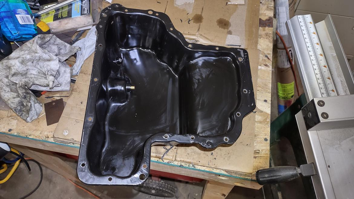
- Procedure: Remove the transmission pan. Replace the old filter with a new one. Clean the transmission pan and install a new gasket. Reinstall the transmission pan, tightening the bolts to the specified torque.
- Tools Needed: Socket set, wrench set, transmission pan gasket, new transmission filter.
3.3.3. Checking for Leaks
Check for any transmission fluid leaks and repair them.
- Procedure: Inspect the transmission case, seals, and lines for any signs of leaks. Repair any leaks by replacing the faulty seals or lines.
- Common Leak Points: Common leak points include the transmission pan gasket, the input shaft seal, and the output shaft seal.
3.4. Updating or Replacing the TCM
If the TCM is found to be faulty or has outdated software, updating or replacing it may be necessary.
3.4.1. Updating TCM Software
Update the TCM software to resolve communication issues.
- Procedure: Use a diagnostic scanner that is capable of performing TCM software updates. Check for any available updates and follow the scanner’s instructions to install them.
- Benefits: Updating the TCM software can improve the transmission’s performance and resolve communication issues.
3.4.2. Replacing the TCM
Replace the TCM if it is found to be irreparably damaged.
- Procedure: Disconnect the battery. Locate the TCM (typically under the dashboard or under a seat). Disconnect the wiring connectors from the TCM. Remove the old TCM. Install the new TCM. Reconnect the wiring connectors. Reconnect the battery.
- Programming: The new TCM may need to be programmed to match your vehicle’s specifications. This typically requires a specialized diagnostic scanner and software.
3.5. Addressing Internal Transmission Issues
If the P0715 code is caused by internal transmission issues, professional repair may be necessary.
3.5.1. Professional Transmission Repair
Take the vehicle to a qualified mechanic for transmission repair.
- Expertise Required: Internal transmission repair requires specialized knowledge and tools. It is best left to experienced professionals.
- Potential Repairs: Potential repairs include replacing worn gears, bearings, or valve bodies.
3.5.2. Transmission Rebuild or Replacement
In severe cases, the transmission may need to be rebuilt or replaced.
- Rebuild: A transmission rebuild involves disassembling the transmission, inspecting all components, replacing worn or damaged parts, and reassembling the transmission.
- Replacement: A transmission replacement involves removing the old transmission and installing a new or remanufactured transmission.
By implementing these practical solutions, you can effectively address the P0715 code and restore your Mercedes to optimal performance. Remember to use high-quality parts and follow proper procedures to ensure lasting repairs.
4. Preventing the P0715 Code: Proactive Measures
Preventing the P0715 code involves taking proactive measures to maintain the health of your transmission system. Regular maintenance and careful attention to your vehicle’s performance can help avoid the issues that trigger this code. Here are key strategies to keep your Mercedes running smoothly.
4.1. Regular Transmission Fluid Maintenance
Consistent transmission fluid maintenance is crucial for preventing transmission problems.
4.1.1. Adhering to Service Intervals
Follow the manufacturer’s recommended service intervals for transmission fluid changes.
- Recommendation: Check your vehicle’s owner’s manual for the recommended service intervals. Typically, transmission fluid should be changed every 30,000 to 60,000 miles, depending on driving conditions.
- Benefits: Regular fluid changes help maintain proper lubrication and cooling, preventing wear and tear on transmission components.
4.1.2. Using the Right Type of Fluid
Use the correct type of transmission fluid specified for your vehicle.
- Importance: Using the wrong type of fluid can cause poor performance and damage to the transmission.
- Verification: Consult your vehicle’s owner’s manual or a trusted mechanic to determine the correct type of transmission fluid.
4.1.3. Monitoring Fluid Condition
Regularly check the condition of the transmission fluid.
- Procedure: Check the fluid level and condition using the transmission fluid dipstick (if equipped). The fluid should be a clear red or pink color. If it appears dark, smells burnt, or contains debris, it needs to be replaced.
- Corrective Action: If the fluid is contaminated, flush and replace it with fresh fluid.
4.2. Inspecting Wiring and Connectors Regularly
Regularly inspect wiring and connectors to ensure they are in good condition.
4.2.1. Visual Inspections
Perform regular visual inspections of the wiring and connectors.
- Procedure: Check the wiring and connectors leading to the input shaft speed sensor and other transmission components. Look for signs of damage, such as frayed wires, corrosion, or loose connections.
- Frequency: Perform these inspections at least once a year, or more frequently if you drive in harsh conditions.
4.2.2. Cleaning Connectors
Clean corroded connectors to ensure a reliable connection.
- Procedure: Disconnect the connector. Use an electrical contact cleaner to clean the terminals. Reconnect the connector and ensure it is securely fastened.
- Benefits: Cleaning connectors helps prevent signal disruptions and ensures proper communication between sensors and the TCM.
4.2.3. Protecting Wiring
Protect wiring from damage by using protective sleeves or conduit.
- Procedure: Use wire sleeves or conduit to protect exposed wiring from abrasion, heat, and other environmental factors.
- Materials: Use high-quality, heat-resistant materials to ensure long-lasting protection.
4.3. Avoiding Harsh Driving Habits
Aggressive driving habits can put excessive stress on the transmission.
4.3.1. Smooth Acceleration and Braking
Practice smooth acceleration and braking to reduce strain on the transmission.
- Technique: Avoid sudden acceleration and hard braking. Gradually increase speed and gently apply the brakes.
- Benefits: Smooth driving habits reduce wear and tear on transmission components and improve fuel efficiency.
4.3.2. Avoiding Overloading the Vehicle
Avoid overloading the vehicle, as this can put excessive strain on the transmission.
- Recommendation: Check your vehicle’s owner’s manual for the maximum load capacity. Avoid exceeding this limit.
- Impact: Overloading the vehicle can cause the transmission to overheat and wear out prematurely.
4.3.3. Proper Towing Practices
If you tow a trailer, follow proper towing practices to protect the transmission.
- Recommendation: Use the correct towing equipment and follow the manufacturer’s recommendations for towing capacity. Use a transmission cooler to help prevent overheating.
- Maintenance: Regularly inspect the towing equipment and transmission for signs of wear or damage.
4.4. Regular Diagnostic Checks
Perform regular diagnostic checks to identify potential issues early.
4.4.1. Using an OBD-II Scanner
Use an OBD-II scanner to check for stored codes.
- Procedure: Connect the scanner to the OBD-II port and retrieve any stored codes. Address any codes promptly to prevent further damage.
- Frequency: Perform diagnostic checks at least twice a year, or more frequently if you notice any unusual symptoms.
4.4.2. Monitoring Transmission Performance
Pay attention to how the transmission is performing.
- Observation: Monitor the transmission for any signs of trouble, such as erratic shifting, harsh shifting, or slipping.
- Corrective Action: If you notice any issues, take the vehicle to a qualified mechanic for inspection and repair.
By implementing these proactive measures, you can significantly reduce the risk of encountering the P0715 code and other transmission problems. Regular maintenance, careful driving habits, and timely diagnostic checks will help keep your Mercedes running smoothly for years to come.
5. The Role of CARDIAGTECH.NET in Addressing the P0715 Code
CARDIAGTECH.NET plays a vital role in helping you address the P0715 code by providing the necessary tools, equipment, and expertise for accurate diagnosis and effective repair. Here’s how CARDIAGTECH.NET supports both professional technicians and DIY enthusiasts in tackling this issue.
5.1. Providing Advanced Diagnostic Tools
CARDIAGTECH.NET offers a wide range of advanced diagnostic tools that are essential for accurately diagnosing the P0715 code.
5.1.1. OBD-II Scanners
High-quality OBD-II scanners are crucial for retrieving diagnostic trouble codes and live data from your vehicle’s computer.
- Features: CARDIAGTECH.NET provides scanners with advanced features such as code reading, code clearing, live data streaming, and freeze frame data.
- Benefits: These scanners allow you to quickly identify the P0715 code and gather valuable information about the transmission’s performance.
5.1.2. Multimeters
Multimeters are essential for testing the input shaft speed sensor, wiring, and connectors.
- Features: CARDIAGTECH.NET offers multimeters with high accuracy and reliability, suitable for both professional and DIY use.
- Benefits: Multimeters allow you to check the sensor’s resistance, voltage, and continuity, helping you pinpoint electrical issues.
5.1.3. Transmission Fluid Testers
Transmission fluid testers help you assess the condition of the transmission fluid.
- Features: CARDIAGTECH.NET provides testers that can measure the fluid’s viscosity, contamination levels, and other important parameters.
- Benefits: These testers help you determine if the transmission fluid needs to be changed or flushed.
5.2. Offering High-Quality Repair Equipment
CARDIAGTECH.NET provides a comprehensive selection of high-quality repair equipment needed to address the P0715 code.
5.2.1. Wiring Repair Kits
Wiring repair kits include everything you need to repair damaged wiring and connectors.
- Contents: Wire strippers, crimping tools, butt connectors, heat shrink tubing, and electrical tape.
- Benefits: These kits make it easy to repair wiring issues and ensure a reliable connection.
5.2.2. Transmission Fluid Flushing Machines
Transmission fluid flushing machines make it easy to flush the transmission fluid and remove contaminants.
- Features: These machines circulate new fluid through the transmission, removing old fluid and debris.
- Benefits: Flushing machines ensure that the transmission is filled with clean, fresh fluid, improving its performance and longevity.
5.2.3. Sensor Replacement Tools
Sensor replacement tools make it easy to remove and install the input shaft speed sensor.
- Types: Socket sets, wrench sets, and specialized sensor sockets.
- Benefits: These tools ensure that the sensor is properly installed and tightened to the correct torque.
5.3. Providing Expert Guidance and Support
CARDIAGTECH.NET offers expert guidance and support to help you diagnose and repair the P0715 code.
5.3.1. Detailed Product Information
CARDIAGTECH.NET provides detailed product information to help you choose the right tools and equipment for your needs.
- Specifications: Detailed specifications, features, and compatibility information for each product.
- Benefits: This information helps you make informed decisions and select the best tools for the job.
5.3.2. Expert Technical Support
CARDIAGTECH.NET offers expert technical support to answer your questions and provide guidance.
- Channels: Phone, email, and online chat support.
- Benefits: Our team of experienced technicians can help you troubleshoot issues, provide repair advice, and recommend the right tools and equipment.
5.3.3. Educational Resources
CARDIAGTECH.NET provides educational resources to help you learn more about automotive diagnostics and repair.
- Content: Articles, videos, and tutorials covering a wide range of topics.
- Benefits: These resources help you expand your knowledge and skills, enabling you to tackle more complex repairs.
5.4. Ensuring Customer Satisfaction
CARDIAGTECH.NET is committed to ensuring customer satisfaction by providing high-quality products, expert support, and a hassle-free shopping experience.
5.4.1. Quality Assurance
CARDIAGTECH.NET offers only high-quality products from trusted brands.
- Testing: All products are thoroughly tested to ensure they meet our high standards.
- Benefits: You can trust that the products you purchase from CARDIAGTECH.NET will perform reliably and effectively.
5.4.2. Easy Returns and Exchanges
CARDIAGTECH.NET offers easy returns and exchanges if you are not satisfied with your purchase.
- Policy: Hassle-free returns and exchanges within 30 days of purchase.
- Benefits: You can shop with confidence, knowing that you can return or exchange products if they do not meet your needs.
5.4.3. Competitive Pricing
CARDIAGTECH.NET offers competitive pricing on all of our products.
- Value: High-quality products at affordable prices.
- Benefits: You can get the tools and equipment you need without breaking the bank.
By providing advanced diagnostic tools, high-quality repair equipment, expert guidance, and a commitment to customer satisfaction, CARDIAGTECH.NET is your trusted partner in addressing the P0715 code and keeping your Mercedes running smoothly.
6. Understanding the Technical Aspects of the P0715 Code
To fully understand and address the P0715 code, it’s essential to delve into the technical aspects of the turbine/input shaft speed sensor and its role in the transmission system. This section provides a detailed explanation of the sensor’s function, the signals it produces, and how the transmission control module (TCM) uses this information to manage gear shifts.
6.1. The Function of the Turbine/Input Shaft Speed Sensor
The turbine/input shaft speed sensor measures the rotational speed of the transmission’s input shaft.
6.1.1. How the Sensor Works
The sensor typically uses a magnetic pickup to detect the passing of teeth on a rotating gear or tone wheel attached to the input shaft.
- Mechanism: As the gear rotates, the teeth interrupt a magnetic field, generating a series of pulses.
- Signal Conversion: These pulses are converted into an electrical signal that represents the speed of the input shaft.
6.1.2. Importance of Accurate Readings
Accurate speed readings are crucial for the TCM to make informed decisions about gear shifts.
- Shift Timing: The TCM uses the input shaft speed, along with other sensor data, to determine the optimal time to shift gears.
- Smooth Transitions: Precise shift timing ensures smooth and efficient gear transitions, enhancing the driving experience.
6.2. Signal Characteristics of the Speed Sensor
The turbine/input shaft speed sensor generates an electrical signal that varies with the rotational speed of the input shaft.
6.2.1. Voltage or Frequency-Based Signals
The sensor may produce either a voltage-based or a frequency-based signal.
- Voltage-Based: The voltage of the signal increases or decreases with the speed of the input shaft.
- Frequency-Based: The frequency of the signal pulses increases with the speed of the input shaft.
6.2.2. Signal Amplitude and Frequency
The amplitude and frequency of the signal provide information about the input shaft speed.
- Amplitude: The amplitude (strength) of the signal must be within a certain range for the TCM to interpret it correctly.
- Frequency: The frequency of the signal pulses is directly proportional to the input shaft speed.
6.2.3. Signal Stability
A stable and consistent signal is necessary for accurate speed readings.
- Noise and Interference: Electrical noise or interference can distort the signal, leading to inaccurate readings.
- Wiring Integrity: Proper wiring and shielding are essential to minimize noise and ensure signal stability.
6.3. The Role of the TCM in Interpreting Sensor Data
The transmission control module (TCM) processes the signal from the turbine/input shaft speed sensor to control gear shifts.
6.3.1. Monitoring Input Shaft Speed
The TCM continuously monitors the input shaft speed to determine the appropriate gear.
- Data Analysis: The TCM analyzes the signal frequency and amplitude to calculate the input shaft speed in revolutions per minute (RPM).
- Comparison: The TCM compares the input shaft speed to other sensor data, such as vehicle speed and throttle position, to determine the optimal gear.
6.3.2. Controlling Gear Shifts
The TCM uses the input shaft speed data to control the transmission’s shift solenoids.
- Shift Solenoids: These solenoids control the flow of hydraulic fluid to the transmission’s clutches and bands, which engage and disengage gears.
- Precise Control: By precisely controlling the shift solenoids, the TCM ensures smooth and efficient gear transitions.
6.3.3. Diagnosing Transmission Problems
The TCM also uses the input shaft speed data to diagnose transmission problems.
- Error Detection: If the input shaft speed is inconsistent with other sensor data, the TCM may detect a problem and set a diagnostic trouble code, such as P0715.
- Troubleshooting: The diagnostic trouble code provides valuable information for troubleshooting the transmission problem.
6.4. Potential Issues Affecting Sensor Signal
Several issues can affect the signal from the turbine/input shaft speed sensor, leading to the P0715 code.
6.4.1. Sensor Malfunction
The sensor itself may be faulty, producing inaccurate or no signal.
- Internal Damage: Internal damage to the sensor can cause it to fail.
- Contamination: Contamination from dirt, debris, or oil can interfere with the sensor’s operation.
6.4.2. Wiring and Connector Problems
Damaged wiring or corroded connectors can disrupt the signal from the sensor.
- Open Circuits: Broken wires can create open circuits, preventing the signal from reaching the TCM.
- Short Circuits: Short circuits can cause the signal to be distorted or lost.
- Corrosion: Corrosion on the connector terminals can increase resistance and weaken the signal.
6.4.3. Mechanical Problems
Mechanical problems within the transmission can affect the sensor’s readings.
- Worn Gears: Worn gears or tone wheels can produce an irregular signal.
- Misalignment: Misalignment of the sensor can cause it to produce inaccurate readings.
By understanding these technical aspects of the turbine/input shaft speed sensor and its role in the transmission system, you can better diagnose and address the P0715 code. CARDIAGTECH.NET provides the tools and resources you need to effectively troubleshoot and repair these issues, ensuring your Mercedes performs at its best.
7. The Economic Impact of Addressing the P0715 Code Promptly
Addressing the P0715 code promptly can have significant economic benefits, preventing more extensive and costly repairs down the line. This section outlines the potential financial implications of ignoring the P0715 code and highlights the economic advantages of timely intervention.
7.1. Potential Costs of Ignoring the P0715 Code
Ignoring the P0715 code can lead to a cascade of problems, resulting in substantial repair costs.
7.1.1. Transmission Damage
Continued operation with a faulty input shaft speed sensor can cause severe damage to the transmission.
- Slipping Gears: Incorrect gear shifts can lead to transmission slipping, causing excessive wear and tear on the clutches and gears.
- Overheating: Slipping gears can also cause the transmission to overheat, leading to further damage.
- Costly Repairs: Repairing or replacing a damaged transmission can cost anywhere from $3,000 to $8,000, depending on the extent of the damage and the vehicle model.
7.1.2. Reduced Fuel Efficiency
A malfunctioning transmission can significantly reduce fuel efficiency.
- Inefficient Gear Shifts: Incorrect gear shifts can cause the engine to work harder, consuming more fuel.
- Increased Fuel Costs: Over time, the increased fuel consumption can add up to significant expenses.
- Example: A decrease in fuel efficiency from 20 MPG to 15 MPG can result in hundreds of dollars in additional fuel costs per year.
7.1.3. Safety Risks
A faulty transmission can pose safety risks.
- Sudden Shifting: Unexpected gear shifts can cause the vehicle to lurch or stall, increasing the risk of accidents.
- Loss of Control: In severe cases, a malfunctioning transmission can cause a loss of control of the vehicle.
7.2. Economic Benefits of Timely Intervention
Addressing the P0715 code promptly can save you money and prevent more serious problems.
7.2.1. Preventing Major Repairs
Replacing a faulty input shaft speed sensor is a relatively inexpensive repair compared to overhauling or replacing a transmission.
- Sensor Cost: The cost of an input shaft speed sensor typically ranges from $50 to $200.
- Labor Costs: Labor costs for replacing the sensor can range from $100 to $300.
- Savings: By addressing the issue early, you can