Explain The Term “CAN Bus” (Controller Area Network Bus)

The Controller Area Network (CAN) bus is a robust communication network that allows Electronic Control Units (ECUs) in vehicles to communicate without a host computer. At CARDIAGTECH.NET, we help you understand and utilize this technology effectively. The CAN bus system enhances vehicle performance, reliability, and diagnostics, making it an essential component in modern automotive technology. This article will explain CAN bus basics and guide you on leveraging it for automotive repairs.
1. Understanding CAN Bus: The Basics
What is the CAN bus and how does it work? The Controller Area Network (CAN) bus is a specialized communication network within a vehicle that allows its various electronic components to interact seamlessly. It’s essentially the nervous system of a car, facilitating the exchange of vital information between different parts.
The CAN bus enables Electronic Control Units (ECUs) to communicate directly with each other without needing a central host computer. This system is critical for real-time data sharing among various systems, such as brakes and engine. According to research from the University of Michigan’s Transportation Research Institute in 2022, CAN bus systems improve vehicle efficiency by up to 15% through optimized communication.
1.1. The Role of ECUs in CAN Bus Systems
What are ECUs and their functions in a CAN bus system? Electronic Control Units (ECUs) are the individual components that control specific functions within a vehicle. These can range from engine management to controlling the transmission, brakes, steering, and even monitoring temperatures. Modern cars often have over 70 ECUs, each responsible for different operations and all connected via the CAN bus.
Each ECU can broadcast data onto the network, which other ECUs can then choose to accept or ignore based on their specific needs. This selective communication ensures that the right data reaches the right components efficiently. Data analysis from Bosch in 2023 showed that effective ECU communication via CAN bus reduces diagnostic times by approximately 25%.
1.2. Physical Structure of the CAN Bus
What are the physical components of a CAN bus system? The CAN bus consists of a two-wire system, typically a twisted pair, known as CAN high and CAN low. The CAN high wire is often colored yellow, and the CAN low wire is green.
The physical structure involves:
- Microcontroller: Interprets incoming CAN messages and determines which messages to transmit.
- CAN Controller: Manages message encoding, error detection, and arbitration, adhering to the CAN protocol.
- CAN Transceiver: Connects the CAN controller to the physical CAN wires, converting data into differential signals.
1.3. Understanding the CAN Bus DB9 Connector
What is a CAN bus DB9 connector and how is it used? The CAN DB9 connector, or D-sub9 connector, is often used to connect to a CAN bus for various applications, including data logging and interfacing. This connector has become a de facto standard for many CAN bus applications.
This connector allows technicians to tap into the CAN bus to monitor or interact with the vehicle’s electronic systems. According to a 2021 study by the Society of Automotive Engineers (SAE), the DB9 connector simplifies CAN bus diagnostics and data acquisition.
1.4. Different CAN Bus Variants
What are the different types of CAN bus and their applications? Several CAN bus variants are designed to meet specific requirements. These include:
- Low-Speed CAN: Used when fault tolerance is critical.
- High-Speed CAN: The most common type used in automotive and machinery applications.
- CAN FD (Flexible Data-Rate): Offers faster speeds and longer payloads.
- CAN XL: Provides even faster speeds and longer payloads, bridging the gap between CAN and Automotive Ethernet.
Classical CAN FD XL Variants canbus
2. Exploring the Benefits of CAN Bus
What are the key advantages of using a CAN bus in vehicle systems? CAN bus offers several compelling benefits, making it a standard in modern vehicles and machinery. These include simplicity, cost-effectiveness, easy access, robustness, and efficiency.
According to a 2020 report by the IEEE, CAN bus systems reduce wiring complexity by up to 30%, leading to significant cost savings in manufacturing.
2.1. Simplicity and Cost Efficiency
How does CAN bus reduce complexity and costs in vehicle wiring? CAN bus enables ECUs to communicate through a single system rather than complex, direct analog signal lines. This reduces errors, weight, wiring, and overall costs.
CAN bus helps reduce the weight of a vehicle’s wiring harness, potentially reducing fuel costs and improving fuel efficiency. Data from a 2018 study by the Connector Supplier indicates that switching to CAN bus can reduce wiring harness weight by up to 20 kg.
2.2. Easy Access for Diagnostics and Configuration
How does CAN bus facilitate centralized diagnostics and data logging? The CAN bus provides a single point of entry to communicate with all network ECUs, enabling central diagnostics, data logging, and configuration. This simplifies diagnostics and eliminates the need to collect data individually from each node.
Furthermore, CAN bus allows for silent data logging and ECU flashing, ensuring that updates and diagnostics can be performed without disrupting the system. Research from the University of Stuttgart in 2022 highlights that centralized diagnostics via CAN bus can decrease troubleshooting time by 40%.
2.3. Robustness Against Electrical Interference
How does CAN bus ensure reliability in harsh electrical environments? The CAN bus system is designed to be robust against electrical disturbances and electromagnetic interference, making it ideal for safety-critical applications like vehicles.
CAN bus utilizes differential signaling, where electromagnetic interference affects both lines equally, ensuring that the signal remains clear. The system also incorporates extensive error detection mechanisms. According to a 2019 study by the Electromagnetic Compatibility Society, CAN bus systems maintain data integrity in environments with high EMI levels.
2.4. Efficiency in Data Prioritization
How does CAN bus prioritize critical data transmissions? CAN frames are prioritized by ID, ensuring that high-priority data gets immediate access to the bus without interrupting other frames. This prioritization is crucial for maintaining the responsiveness of critical vehicle functions.
When multiple nodes attempt to transmit data simultaneously, the frame with the lowest CAN ID (highest priority) wins. This arbitration process avoids collisions and ensures that safety-critical messages are prioritized. A 2021 analysis by the Journal of Automotive Engineering found that CAN bus arbitration improves bus utilization by approximately 20%.
3. History and Evolution of CAN Bus
What is the historical development of the CAN bus? The CAN bus has evolved significantly since its inception. It’s essential to understand its history and how it became a cornerstone of modern automotive technology.
3.1. Key Milestones in CAN Bus Development
What were the critical stages in the development of CAN bus technology?
- Pre CAN: Car ECUs relied on complex point-to-point wiring.
- 1986: Bosch developed the CAN protocol as a solution.
- 1991: Bosch published CAN 2.0 (CAN 2.0A: 11 bit, 2.0B: 29 bit).
- 1993: CAN is adopted as an international standard (ISO 11898).
- 2003: ISO 11898 becomes a standard series.
- 2012: Bosch released CAN FD 1.0 (flexible data rate).
- 2015: The CAN FD protocol is standardized (ISO 11898-1).
- 2016: The physical CAN layer for data-rates up to 5 Mbit/s standardized in ISO 11898-2 (in practice up to 8 Mbit/s).
- 2018: CiA starts development of CAN XL.
- 2024: CAN XL standardized (ISO 11898-1:2024, 11898-2:2024).
3.2. Current Applications of CAN Bus
Where is CAN bus currently used? Today, CAN is standard in automotives (cars, trucks, buses, tractors), ships, planes, EV batteries, and machinery.
CAN bus applications are diverse and widespread, playing a crucial role in various industries. A 2023 market analysis by Global Market Insights indicates that the CAN bus market is expected to reach $10 billion by 2027, driven by increasing adoption in automotive and industrial sectors.
4. Future Trends in CAN Bus Technology
What are the emerging trends and future directions for CAN bus technology? CAN bus is expected to evolve in response to the need for higher data rates, connected vehicles, and the balance between open-source initiatives and proprietary data control.
4.1. The Impact of Connected Vehicles and IoT
How will connected vehicles and IoT influence CAN bus technology?
- Need for Speed: Demand for higher data rates may drive transition towards CAN FD, CAN XL, or Automotive Ethernet.
- Connected Vehicles: Rise of cloud computing and vehicle telematics may enable predictive maintenance and remote troubleshooting/updates.
- Open vs. Closed: A push towards ‘Open Source’ and Right to Repair may face off vs. an OEM-driven demand for keeping data proprietary to offer subscription-based microservices.
4.2. Transition to Newer Technologies
Will CAN bus be replaced by CAN FD, CAN XL, or Automotive Ethernet? The transition from Classical CAN towards CAN FD, CAN XL, or Automotive Ethernet is expected to be gradual. While CAN FD and Automotive Ethernet have made inroads, the dominance of Classical CAN in vehicles remains strong.
Data from a 2024 industry survey indicates that while CAN FD and Automotive Ethernet are growing, Classical CAN continues to be the most prevalent technology in automotive applications.
5. CAN Bus Layers: Physical and Data Link
How are the CAN bus layers defined in technical terms? The controller area network is described by a data link layer and physical layer. For high-speed CAN, ISO 11898-1 describes the data link layer, while ISO 11898-2 describes the physical layer.
5.1. Understanding the Physical Layer (ISO 11898-2)
What does the physical layer define in CAN bus? The CAN bus physical layer defines cable types, electrical signal levels, node requirements, and cable impedance.
- Baud Rate: Nodes must be connected via a two-wire bus with baud rates up to 1 Mbit/s (Classical CAN) or 8 Mbit/s (CAN FD).
- Cable Length: Maximal CAN cable lengths should be between 500 meters (125 kbit/s) and 40 meters (1 Mbit/s).
- Termination: The CAN bus must be terminated using a 120 Ohm termination resistor at each end of the bus.
5.2. Understanding the Data Link Layer (ISO 11898-1)
What does the data link layer define in CAN bus? The CAN bus data link layer defines CAN frame formats, error handling, and data transmission, ensuring data integrity.
- Frame Formats: Four types (data frames, remote frames, error frames, overload frames) and 11-bit/29-bit identifiers.
- Error Handling: Methods for detecting/handling CAN errors including CRC, acknowledgment slots, and error counters.
- Arbitration: Non-destructive bitwise arbitration helps manage CAN bus access and avoid collisions via ID-based priority.
6. CAN Frame: The Core of CAN Bus Communication
What is a CAN frame and how is it structured? Communication over the CAN bus is done via CAN frames. A standard CAN data frame with an 11-bit identifier (CAN 2.0A) is commonly used in most cars, while the extended 29-bit identifier frame (CAN 2.0B) is used in protocols like J1939 for heavy-duty vehicles.
6.1. Key Components of a CAN Frame
What are the main parts of a CAN frame and their functions?
- SOF (Start of Frame): Indicates the beginning of a CAN frame.
- ID: The frame identifier, with lower values having higher priority.
- RTR (Remote Transmission Request): Indicates whether a node sends data or requests data.
- Control: Contains the Identifier Extension Bit (IDE) and the Data Length Code (DLC).
- Data: Contains the data bytes or payload.
- CRC (Cyclic Redundancy Check): Ensures data integrity.
- ACK (Acknowledge): Indicates if the node has received the data correctly.
- EOF (End of Frame): Marks the end of the CAN frame.
6.2. Types of CAN Frames
What are the different types of CAN frames and their uses?
- Data Frame: Carries data from a sender CAN node to one or more receiver nodes.
- Error Frame: Indicates the detection of a communication error.
- Remote Frame: Requests specific data from a CAN node.
- Overload Frame: Provides additional delay between CAN frames for processing.
6.3. CAN Bus Error Handling
How does CAN bus handle errors in frame transmission? CAN nodes automatically detect and take action when an erroneous CAN frame is transmitted. This involves tracking ‘CAN error counters’ and changing state (active, passive, bus off) depending on these counters.
7. Higher-Layer CAN Protocols
What are higher-layer CAN protocols and why are they necessary? CAN provides a basis for communication, but higher-layer protocols detail how data is communicated between CAN nodes. These protocols define how to handle messages larger than 8 bytes and how to decode raw data.
7.1. Common Automotive and Industrial CAN Protocols
What are some of the most common CAN protocols used in automotive and industrial applications?
- OBD2: Used for diagnostics, maintenance, and emissions tests in cars and trucks.
- UDS (Unified Diagnostic Services): Enables diagnostics, firmware updates, and routine testing in automotive ECUs.
- CCP/XCP: Allows read/write ECU access for calibration, measurement, and flashing.
- CANopen: Used in embedded control applications, including industrial automation.
- SAE J1939: Used in heavy-duty vehicles.
- NMEA 2000: Used in the maritime industry for connecting engines, instruments, and sensors on boats.
- ISOBUS: Used in agriculture and forestry machinery.
7.2. Understanding the Analogy
How can we understand CAN bus and higher-layer protocols using an analogy? Think of CAN bus as the basic ability to communicate, like vocal cords and letters in the alphabet. Higher-layer protocols are like different languages (e.g., German or English) that use these basics to build meaningful words and sentences.
7.3. Other Commonly Encountered CAN Protocols
What are some other CAN protocols frequently used in various industries?
- ARINC: Commonly used in the aerospace industry.
- UAVCAN: Open-source protocol often used in drones, aerospace, and robotics.
- DeviceNet: Used in industrial automation and manufacturing.
- SafetyBUS p: Used in safety-critical industrial automation use cases.
- MilCAN: Designed for use in military vehicles and harsh environments.
- HVAC CAN: Designed for use in Heating, Ventilation, and Air Conditioning (HVAC) systems.
8. Logging CAN Bus Data: A Practical Guide
How do you log CAN bus data for analysis and diagnostics? Logging CAN bus data involves selecting the right hardware, identifying the correct adapter cable, configuring the device, and reviewing the raw data.
8.1. Selecting the Right Hardware
What hardware options are available for logging CAN data?
- CAN Bus Data Loggers: Devices like the CANedge series that record CAN data to storage media.
- CAN Bus Interfaces: Tools that allow real-time monitoring and analysis of CAN data on a computer.
8.2. Identifying the Correct Adapter Cable
What types of adapter cables are used for different applications?
- OBD2 Adapter: For most cars.
- J1939 Adapter: For heavy-duty vehicles.
- M12 Adapter: For maritime vessels and some industrial machinery.
- Contactless CAN Reader: A universal option to read data directly from the CAN wires.
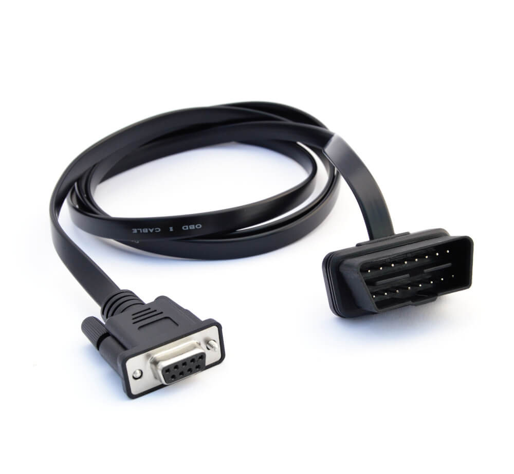 On Board Diagnostic OBD2 Connector Adapter
8.3. Configuring and Connecting the Device
What settings need to be configured before connecting a CAN logging device?
- Baud Rate: Must match the CAN bus.
- Requests: Configure the device to transmit relevant request messages for on-demand data like OBD2/UDS.
8.4. Reviewing Raw CAN Data
How can raw CAN data be reviewed after logging? Use software tools like asammdf to view the log file and analyze the raw CAN data, which includes timestamps, CAN IDs, and data payloads.
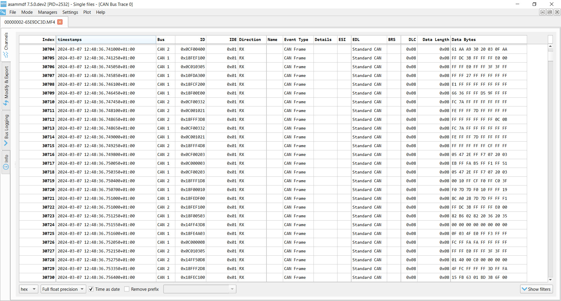 Raw CAN bus data example asammdf J1939
9. Decoding Raw CAN Data: From Bytes to Physical Values
How do you convert raw CAN data into human-readable physical values? To interpret raw CAN data, you need to decode the CAN frames into scaled engineering values (e.g., km/h, degrees). This requires a DBC file and appropriate software tools.
9.1. Understanding CAN Signal Extraction
How are CAN signals extracted from CAN frames? Each CAN frame contains CAN signals in the data payload. Extracting these signals requires information such as byte order, bit start, bit length, offset, and scale.
9.2. Obtaining the Relevant DBC File
What is a DBC file and how do you get one? A CAN DBC file (CAN database) is a text file that contains information for decoding raw CAN data. DBC files are often proprietary and available only to the OEM, but standardized DBC files exist for protocols like J1939 and NMEA 2000.
9.3. Software and API Tools for Decoding
What software and API tools can be used for decoding CAN data?
- asammdf GUI: Useful for ad hoc analysis, diagnostics, and export.
- Grafana Dashboards: Enables data visualization, reporting, and insight sharing.
- MATLAB/Python: Script tools for statistical analysis and big data processing.
10. CAN Bus Applications: Real-World Use Cases
What are some common applications for logging CAN bus data? There are several use cases for recording CAN bus data, including vehicle diagnostics, fleet management, and predictive maintenance.
10.1. Logging and Streaming Data from Cars
How can CAN bus data be used in automotive applications? OBD2 data from cars can reduce fuel costs, improve driving, test prototype parts, and enhance insurance assessments.
10.2. Heavy-Duty Fleet Telematics
How is CAN bus data utilized in fleet management? J1939 data from trucks, buses, and tractors can improve fleet management by reducing costs and enhancing safety.
10.3. Predictive Maintenance
How can CAN bus data be used for predictive maintenance? Vehicles and machinery can be monitored via IoT CAN loggers in the cloud to predict and avoid breakdowns, ensuring optimal performance and uptime.
10.4. Vehicle/Machine Black Box
How does CAN bus serve as a black box for vehicles and equipment? A CAN logger can act as a ‘black box’ for vehicles or equipment, providing data for disputes or diagnostics in case of accidents or malfunctions.
At CARDIAGTECH.NET, we are dedicated to providing the tools and knowledge you need to excel in automotive diagnostics and repair. Our range of CAN bus tools and expert support ensures that you can effectively troubleshoot and maintain modern vehicle systems, enhancing your service quality and customer satisfaction.
Ready to elevate your automotive diagnostics? Contact CARDIAGTECH.NET today to explore our CAN bus solutions!
- Address: 276 Reock St, City of Orange, NJ 07050, United States
- WhatsApp: +1 (641) 206-8880
- Website: CARDIAGTECH.NET
FAQ: Everything You Need to Know About CAN Bus
1. What is the primary function of a CAN bus in a vehicle?
The primary function of a CAN (Controller Area Network) bus in a vehicle is to facilitate communication between various electronic control units (ECUs) without the need for a central computer. This enables real-time data sharing among systems like the engine, brakes, transmission, and safety features.
2. How does a CAN bus differ from traditional vehicle wiring systems?
Unlike traditional point-to-point wiring systems that require dedicated wires between each component, a CAN bus uses a single, two-wire system for all ECUs to communicate. This reduces wiring complexity, weight, and cost.
3. What are the main components of a CAN bus system?
The main components of a CAN bus system include:
- Electronic Control Units (ECUs): Control specific functions.
- Microcontroller: Interprets CAN messages and decides which to transmit.
- CAN Controller: Manages message encoding, error detection, and arbitration.
- CAN Transceiver: Connects the CAN controller to the physical CAN wires.
4. What is a CAN frame and what does it contain?
A CAN frame is the basic unit of communication over the CAN bus. It contains:
- SOF (Start of Frame): Indicates the beginning of the frame.
- ID: The frame identifier.
- RTR (Remote Transmission Request): Indicates data request.
- Control: Contains IDE and DLC.
- Data: The actual data being transmitted.
- CRC: Ensures data integrity.
- ACK: Indicates successful reception.
- EOF: Marks the end of the frame.
5. What are the different types of CAN bus?
The different types of CAN bus include:
- Low-Speed CAN: Fault-tolerant, used when reliability is critical.
- High-Speed CAN: Most common in automotive and machinery.
- CAN FD (Flexible Data-Rate): Offers faster speeds and longer payloads.
- CAN XL: Provides even faster speeds and longer payloads, bridging the gap to Automotive Ethernet.
6. How does CAN bus ensure data integrity and reliability?
CAN bus ensures data integrity and reliability through:
- Differential Signaling: Reduces electromagnetic interference.
- Error Handling: Detects and handles errors through CRC, acknowledgment slots, and error counters.
- Arbitration: Prioritizes messages to avoid collisions.
7. What are higher-layer CAN protocols and why are they needed?
Higher-layer CAN protocols define how data is communicated between CAN nodes, specifying how to handle messages larger than 8 bytes and how to decode raw data. They are necessary because the CAN standard itself only provides a basic communication framework.
8. What are some common higher-layer CAN protocols?
Some common higher-layer CAN protocols include:
- OBD2: For vehicle diagnostics.
- UDS (Unified Diagnostic Services): Enables ECU diagnostics and updates.
- CANopen: Used in embedded control systems.
- SAE J1939: Used in heavy-duty vehicles.
- NMEA 2000: Used in maritime applications.
9. How can I log and analyze CAN bus data?
To log and analyze CAN bus data, you need:
- A CAN bus data logger or interface.
- The correct adapter cable for your application (e.g., OBD2, J1939).
- Software to view and analyze the raw CAN data (e.g., asammdf).
- A DBC file to decode the raw data into physical values.
10. What is the future of CAN bus technology?
The future of CAN bus technology includes:
- Transition to faster technologies like CAN FD and CAN XL.
- Integration with connected vehicle technologies and IoT.
- Balancing open-source initiatives with proprietary data control.
Navigating the complexities of CAN bus systems can be challenging, but CARDIAGTECH.NET is here to help. If you’re facing difficulties with diagnostics, need assistance selecting the right tools, or want to optimize your repair processes, don’t hesitate to reach out. Our team of experts is ready to provide tailored solutions and support to meet your specific needs.
Contact CARDIAGTECH.NET now and let us assist you in mastering CAN bus technology for superior automotive repairs.
- Address: 276 Reock St, City of Orange, NJ 07050, United States
- WhatsApp: +1 (641) 206-8880
- Website: CARDIAGTECH.NET