**How to Diagnose the CAN Network System Using XENTRY: A Comprehensive Guide**
Diagnosing Controller Area Network (CAN) bus issues effectively using XENTRY diagnostic software is crucial for modern automotive repairs. CARDIAGTECH.NET provides you with a detailed exploration of how to diagnose CAN network problems using XENTRY, ensuring accurate and efficient vehicle servicing. Understanding this process not only improves diagnostic accuracy but also enhances the overall efficiency of your automotive repair operations.
1. What is the CAN Network System and Why is Accurate Diagnosis Essential?
The CAN network system is a critical communication backbone in modern vehicles, allowing various electronic control units (ECUs) to communicate with each other. Accurate diagnosis of this system is essential to ensure all vehicle components function correctly. CARDIAGTECH.NET emphasizes the importance of understanding this system for effective vehicle maintenance and repair.
1.1. What is the CAN Network?
The Controller Area Network (CAN) is a robust vehicle bus standard designed to allow microcontrollers and devices to communicate with each other in applications without a host computer. It is a message-based protocol, originally designed for use in automobiles, but also used in many other contexts.
1.2. Why is Accurate CAN Network Diagnosis Critical?
Accurate diagnosis of the CAN network is critical for several reasons:
- Ensures Proper Vehicle Functionality: The CAN network facilitates communication between various ECUs, and any disruption can lead to vehicle malfunctions.
- Prevents Systemic Failures: Addressing CAN network issues promptly prevents cascading failures in interconnected systems.
- Enhances Vehicle Safety: Many safety features rely on the CAN network, making its proper functioning essential for vehicle safety.
- Reduces Repair Costs: Accurate and early diagnosis can prevent more extensive and costly repairs down the line.
- Improves Diagnostic Efficiency: Accurate diagnosis reduces the time needed to identify and fix issues, improving overall workshop efficiency.
1.3. What are the Implications of Poor Diagnosis?
Poor or inaccurate diagnosis of the CAN network can lead to:
- Increased Downtime: Incorrect diagnoses can lead to prolonged repair times, keeping vehicles out of service longer.
- Higher Repair Costs: Misdiagnoses can result in unnecessary parts replacements and labor costs.
- Customer Dissatisfaction: Inaccurate repairs can lead to repeat visits and dissatisfied customers.
- Potential Safety Risks: Misdiagnosed or unaddressed CAN network issues can compromise vehicle safety.
- Damage to Vehicle Systems: Incorrect repairs can potentially damage other interconnected vehicle systems.
2. Understanding the Role of XENTRY in CAN Network Diagnostics
XENTRY is the official diagnostic software used by Mercedes-Benz and other Daimler brands. It provides comprehensive capabilities for diagnosing and troubleshooting complex electronic systems, including the CAN network. CARDIAGTECH.NET highlights how XENTRY enhances the diagnostic process, making it more precise and efficient.
2.1. What is XENTRY?
XENTRY is a comprehensive diagnostic system used for Mercedes-Benz and other Daimler vehicles. It provides access to a wide range of diagnostic functions, including reading fault codes, accessing live data, performing control unit adaptations, and conducting system tests.
2.2. How Does XENTRY Facilitate CAN Network Diagnostics?
XENTRY facilitates CAN network diagnostics through several key features:
- Comprehensive Fault Code Reading: XENTRY can read and interpret fault codes specific to the CAN network, providing insights into potential issues.
- Real-Time Data Monitoring: It allows technicians to monitor real-time data from various ECUs, helping to identify communication issues and data inconsistencies.
- Network Topology Visualization: XENTRY can display the CAN network topology, showing all connected ECUs and their communication pathways.
- Guided Diagnostics: The software provides guided diagnostic procedures, walking technicians through step-by-step troubleshooting processes.
- Control Unit Programming: XENTRY allows for the programming and updating of ECUs, which can resolve software-related CAN network issues.
- Specialized Tests: It includes specialized tests for CAN network components, such as resistance tests and signal analysis.
2.3. What are the Key Benefits of Using XENTRY for CAN Diagnostics?
Using XENTRY for CAN network diagnostics offers several benefits:
- Accuracy: XENTRY provides precise diagnostic information, reducing the likelihood of misdiagnosis.
- Efficiency: Its guided diagnostic procedures and real-time data monitoring streamline the troubleshooting process.
- Comprehensive Coverage: XENTRY covers a wide range of Mercedes-Benz and Daimler vehicles, ensuring broad applicability.
- Integration: The software integrates seamlessly with other diagnostic tools and resources, enhancing overall diagnostic capabilities.
- Up-to-Date Information: XENTRY is regularly updated with the latest vehicle data and diagnostic procedures, ensuring technicians have access to the most current information.
3. Essential Tools and Equipment for CAN Network Diagnosis with XENTRY
To effectively diagnose CAN network issues using XENTRY, it’s important to have the right tools and equipment. CARDIAGTECH.NET offers a range of diagnostic tools to support your CAN network diagnostics.
3.1. What are the Basic Tools Required?
The basic tools required for CAN network diagnostics include:
- XENTRY Diagnostic System: This includes the XENTRY software, a diagnostic interface (such as a XENTRY Diagnosis Pad or Compact 4), and necessary cables.
- Multimeter: A high-quality multimeter is essential for measuring voltage, resistance, and continuity in the CAN network.
- Oscilloscope: An oscilloscope is used to visualize and analyze the CAN bus signals, helping to identify signal integrity issues.
- Breakout Box: A breakout box allows for easy access to the CAN bus wires for testing without damaging the wiring harness.
- CAN Bus Tester: A specialized CAN bus tester can simulate network traffic and test ECU communication.
3.2. What Advanced Tools Can Enhance the Diagnostic Process?
Advanced tools that can enhance the diagnostic process include:
- Network Analyzer: A network analyzer captures and analyzes CAN bus traffic, providing detailed insights into network communication.
- Signal Generator: A signal generator can be used to simulate CAN bus signals and test ECU responses.
- Thermal Imager: A thermal imager can detect overheating components or wiring, which may indicate network issues.
- Data Logger: A data logger records CAN bus data over time, allowing for analysis of intermittent issues.
3.3. How Does CARDIAGTECH.NET Support Your Diagnostic Needs?
CARDIAGTECH.NET supports your diagnostic needs by providing:
- High-Quality Diagnostic Tools: We offer a range of XENTRY diagnostic systems and compatible tools designed for CAN network diagnostics.
[Image of High-Quality Diagnostic Tools]
Alt text: High-quality automotive diagnostic tools from CARDIAGTECH.NET, essential for accurate CAN network diagnosis. - Expert Technical Support: Our team of experts provides technical support to help you with your diagnostic challenges.
- Training Resources: We offer training resources and guides to help you master CAN network diagnostics using XENTRY.
- Tool Recommendations: We provide recommendations on the best tools and equipment for your specific diagnostic needs.
- Competitive Pricing: We offer competitive pricing on our diagnostic tools, ensuring you get the best value for your investment.
Contact CARDIAGTECH.NET at 276 Reock St, City of Orange, NJ 07050, United States, or call us on Whatsapp at +1 (641) 206-8880 for expert advice and support. Visit our website at CARDIAGTECH.NET to explore our full range of diagnostic tools.
4. Step-by-Step Guide to Diagnosing CAN Network Issues with XENTRY
To effectively diagnose CAN network issues with XENTRY, follow this step-by-step guide provided by CARDIAGTECH.NET. This guide ensures a systematic approach to identifying and resolving problems within the CAN network, enhancing diagnostic accuracy and efficiency.
4.1. Step 1: Initial Assessment and Vehicle Preparation
- Connect XENTRY: Connect the XENTRY diagnostic system to the vehicle’s OBD-II port.
- Verify Connection: Ensure that XENTRY establishes a stable connection with the vehicle.
- Identify Vehicle: Allow XENTRY to automatically identify the vehicle model and year.
- Check Battery Voltage: Verify that the vehicle battery voltage is within the acceptable range (typically 12-14V).
- Note Symptoms: Document any symptoms or issues reported by the vehicle owner.
4.2. Step 2: Reading and Interpreting Fault Codes
- Access Fault Memory: Use XENTRY to access the fault memory of all relevant ECUs.
- Record Fault Codes: Record all active and stored fault codes related to the CAN network.
- Interpret Fault Codes: Use XENTRY’s fault code descriptions to understand the nature of each fault.
- Prioritize Faults: Prioritize faults based on their severity and relevance to the reported symptoms.
- Clear Fault Codes: Clear the fault codes and perform a test drive to see which faults reappear.
4.3. Step 3: Analyzing the CAN Network Topology
- Access Network Topology: Use XENTRY to access the CAN network topology view.
- Identify ECUs: Identify all ECUs connected to the CAN network.
- Check Communication Status: Verify the communication status of each ECU.
- Look for Disconnections: Identify any ECUs that are not communicating or have intermittent communication.
- Inspect Wiring Diagrams: Refer to vehicle-specific wiring diagrams to understand the physical layout of the CAN network.
4.4. Step 4: Monitoring Real-Time Data
- Select Data Parameters: Choose relevant data parameters to monitor, such as CAN bus voltage, data transmission rates, and ECU communication status.
- Monitor Data Streams: Monitor the selected data streams in real-time using XENTRY.
- Identify Anomalies: Look for anomalies such as voltage drops, signal interruptions, or data inconsistencies.
- Compare Data: Compare the data with known good values or specifications.
- Record Data: Record the data for further analysis, especially when troubleshooting intermittent issues.
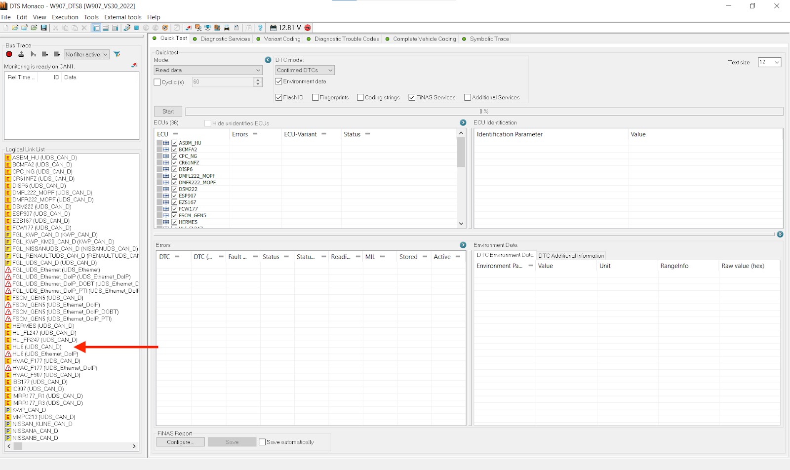
[Image of Monitoring Real-Time Data]
Alt text: Monitoring real-time CAN bus data with XENTRY to identify voltage drops and signal interruptions.
4.5. Step 5: Performing Component Tests
- Access Component Tests: Use XENTRY to access component-specific tests for CAN network components.
- Perform Resistance Tests: Perform resistance tests on the CAN bus wires to check for shorts or open circuits.
- Check Signal Integrity: Use an oscilloscope to check the signal integrity of the CAN bus signals.
- Test ECU Functionality: Test the functionality of individual ECUs using XENTRY’s diagnostic functions.
- Verify Ground Connections: Verify the integrity of ground connections for all ECUs and CAN network components.
4.6. Step 6: Utilizing Guided Diagnostics
- Access Guided Diagnostics: Use XENTRY’s guided diagnostics feature for specific fault codes or symptoms.
- Follow Instructions: Follow the step-by-step instructions provided by XENTRY.
- Perform Tests: Perform the recommended tests and measurements.
- Analyze Results: Analyze the results and follow the recommended troubleshooting steps.
- Document Findings: Document all findings and actions taken during the guided diagnostic process.
4.7. Step 7: Programming and Updating ECUs
- Check for Updates: Use XENTRY to check for available software updates for ECUs.
- Backup Data: Back up any critical data before programming or updating ECUs.
- Follow Procedures: Follow the recommended programming and updating procedures.
- Verify Functionality: Verify the functionality of the ECUs after programming or updating.
- Clear Fault Codes: Clear any fault codes that may have been generated during the programming process.
4.8. Step 8: Final Verification and System Validation
- Perform a Test Drive: Perform a test drive to verify that the issues have been resolved.
- Monitor Data: Monitor CAN network data during the test drive.
- Check Fault Codes: Check for any recurring fault codes.
- Validate System: Validate that all systems are functioning correctly.
- Provide Documentation: Provide the vehicle owner with documentation of the diagnostic and repair procedures.
5. Common CAN Network Problems and How to Address Them with XENTRY
Understanding common CAN network problems and knowing how to address them with XENTRY is vital for efficient vehicle maintenance. CARDIAGTECH.NET offers insights into common issues and their diagnostic solutions.
5.1. What are Common CAN Network Issues?
Common CAN network issues include:
- Wiring Problems: These include shorts, open circuits, and corroded connectors.
- ECU Failures: Failures of individual ECUs can disrupt network communication.
- Software Glitches: Software bugs or corrupted firmware can cause communication problems.
- Bus Overload: Too much data traffic on the CAN bus can lead to communication errors.
- Termination Resistor Problems: Incorrect or missing termination resistors can cause signal reflections and communication issues.
- Power Supply Issues: Voltage drops or fluctuations can affect ECU communication.
5.2. How Can Wiring Problems be Addressed?
Wiring problems can be addressed using XENTRY and a multimeter:
- Visual Inspection: Inspect the wiring harness for visible damage or corrosion.
- Continuity Tests: Use a multimeter to perform continuity tests on the CAN bus wires.
- Resistance Tests: Measure the resistance of the CAN bus wires to check for shorts or open circuits.
- Voltage Tests: Check the voltage levels on the CAN bus wires.
- Repair or Replace: Repair or replace any damaged wiring or connectors.
- Verify Communication: Use XENTRY to verify that communication has been restored.
5.3. How Can ECU Failures be Diagnosed?
ECU failures can be diagnosed using XENTRY:
- Fault Code Analysis: Read and interpret fault codes related to specific ECUs.
- Real-Time Data Monitoring: Monitor real-time data from the ECU to check for anomalies.
- Component Tests: Perform component-specific tests on the ECU using XENTRY.
- ECU Programming: Try reprogramming the ECU to resolve software glitches.
- Replacement: If the ECU is faulty, replace it and program it with the correct software.
- Verify Communication: Use XENTRY to verify that communication has been restored with the new ECU.
5.4. How Can Software Glitches be Resolved?
Software glitches can be resolved using XENTRY:
- Check for Updates: Check for available software updates for the ECU.
- Perform Programming: Use XENTRY to program the ECU with the latest software.
- Clear Fault Codes: Clear any fault codes that may have been generated during the programming process.
- Test Functionality: Test the functionality of the ECU after programming.
- Verify Communication: Use XENTRY to verify that communication has been restored.
5.5. How Can Bus Overload Issues be Managed?
Bus overload issues can be managed by:
- Identifying the Source: Use a network analyzer to identify the source of the excessive data traffic.
- Optimizing Data Transmission: Optimize the data transmission rates of ECUs to reduce bus load.
- Filtering Data: Filter unnecessary data from the CAN bus.
- Upgrading Hardware: Upgrade the CAN bus hardware to support higher data rates.
- Redesigning Network: Redesign the network topology to distribute the data load more evenly.
5.6. How Can Termination Resistor Problems be Corrected?
Termination resistor problems can be corrected by:
- Checking Resistance: Use a multimeter to check the resistance of the termination resistors (typically 120 ohms).
- Verifying Placement: Verify that the termination resistors are properly placed at the ends of the CAN bus.
- Replacing Resistors: Replace any faulty or missing termination resistors.
- Testing Communication: Test the CAN bus communication after replacing the resistors.
[Image of Termination Resistors]
Alt text: Checking and verifying the placement of termination resistors in the CAN bus system for proper communication.
5.7. How Can Power Supply Issues be Resolved?
Power supply issues can be resolved by:
- Checking Voltage Levels: Use a multimeter to check the voltage levels at the ECUs.
- Inspecting Wiring: Inspect the wiring and connectors for corrosion or damage.
- Testing Ground Connections: Test the integrity of ground connections.
- Replacing Components: Replace any faulty power supply components or wiring.
- Verifying Stability: Verify the stability of the power supply after making repairs.
6. Advanced Diagnostic Techniques for Complex CAN Network Issues
For complex CAN network issues, advanced diagnostic techniques are necessary. CARDIAGTECH.NET provides insights into these techniques to help you tackle even the most challenging diagnostic scenarios.
6.1. What are Advanced Diagnostic Techniques?
Advanced diagnostic techniques include:
- Network Analysis: Using a network analyzer to capture and analyze CAN bus traffic.
- Signal Analysis: Using an oscilloscope to analyze the CAN bus signals in detail.
- Simulation: Simulating CAN bus signals to test ECU responses.
- Data Logging: Recording CAN bus data over time to analyze intermittent issues.
- Bench Testing: Testing ECUs on a bench setup to isolate problems.
- Advanced Fault Code Interpretation: Understanding and interpreting complex fault code combinations.
6.2. How is Network Analysis Performed?
Network analysis is performed by:
- Connecting Analyzer: Connecting a network analyzer to the CAN bus.
- Capturing Data: Capturing CAN bus traffic data.
- Analyzing Data: Analyzing the data to identify communication patterns, errors, and anomalies.
- Identifying Issues: Identifying the source of the communication problems.
- Documenting Findings: Documenting the findings and developing a diagnostic plan.
6.3. How is Signal Analysis Conducted?
Signal analysis is conducted by:
- Connecting Oscilloscope: Connecting an oscilloscope to the CAN bus wires.
- Capturing Signals: Capturing the CAN bus signals.
- Analyzing Waveforms: Analyzing the waveforms to check for signal integrity issues, such as reflections, noise, or distortion.
- Identifying Problems: Identifying the cause of the signal problems.
- Documenting Findings: Documenting the findings and developing a diagnostic plan.
6.4. How is Simulation Used in Diagnostics?
Simulation is used in diagnostics by:
- Creating Simulations: Creating simulations of CAN bus signals using a signal generator.
- Testing ECUs: Testing the responses of ECUs to the simulated signals.
- Identifying Issues: Identifying issues with ECU functionality or communication.
- Verifying Repairs: Verifying the effectiveness of repairs by simulating signals and monitoring ECU responses.
6.5. How is Data Logging Used?
Data logging is used by:
- Connecting Logger: Connecting a data logger to the CAN bus.
- Recording Data: Recording CAN bus data over time.
- Analyzing Data: Analyzing the data to identify intermittent issues or trends.
- Identifying Problems: Identifying the cause of the intermittent problems.
- Documenting Findings: Documenting the findings and developing a diagnostic plan.
6.6. How is Bench Testing Performed?
Bench testing is performed by:
- Removing ECU: Removing the ECU from the vehicle.
- Setting Up Bench: Setting up a bench testing environment with power supplies, signal generators, and diagnostic tools.
- Testing ECU: Testing the ECU functionality and communication in the controlled environment.
- Identifying Issues: Identifying issues with the ECU that may not be apparent in the vehicle.
- Verifying Repairs: Verifying the effectiveness of repairs by testing the ECU on the bench.
7. Best Practices for Maintaining the CAN Network System
Maintaining the CAN network system through best practices ensures vehicle reliability and longevity. CARDIAGTECH.NET recommends these practices to keep your CAN network in optimal condition.
7.1. What are the Key Maintenance Practices?
Key maintenance practices include:
- Regular Inspections: Conducting regular visual inspections of the wiring and connectors.
- Proper Wiring Management: Ensuring that wiring is properly routed and secured to prevent damage.
- Connector Maintenance: Keeping connectors clean and free from corrosion.
- Software Updates: Keeping ECU software up-to-date.
- Preventive Diagnostics: Performing preventive diagnostic scans to identify potential issues early.
- Protection: Protecting the CAN network components from environmental factors.
7.2. How Should Wiring be Inspected?
Wiring should be inspected by:
- Visual Checks: Visually checking for damage, such as cuts, abrasions, or kinks.
- Checking Connectors: Checking connectors for corrosion, loose connections, or damage.
- Testing Continuity: Testing the continuity of wires to check for open circuits.
- Measuring Resistance: Measuring the resistance of wires to check for shorts or excessive resistance.
- Repairing Damage: Repairing or replacing any damaged wiring or connectors.
7.3. How Should Connectors be Maintained?
Connectors should be maintained by:
- Cleaning: Cleaning connectors with a specialized electronic cleaner.
- Applying Dielectric Grease: Applying dielectric grease to protect against corrosion.
- Ensuring Secure Connections: Ensuring that connectors are securely connected.
- Replacing Damaged Connectors: Replacing any damaged or corroded connectors.
7.4. Why are Software Updates Important?
Software updates are important because they:
- Fix Bugs: Fix known software bugs that can cause communication problems.
- Improve Performance: Improve the performance and efficiency of the CAN network.
- Enhance Security: Enhance the security of the CAN network.
- Add Features: Add new features and functionality to the ECUs.
- Ensure Compatibility: Ensure compatibility with other vehicle systems.
7.5. How Can Preventive Diagnostics Help?
Preventive diagnostics can help by:
- Identifying Issues Early: Identifying potential issues before they become major problems.
- Reducing Downtime: Reducing downtime by addressing issues proactively.
- Lowering Repair Costs: Lowering repair costs by preventing major failures.
- Improving Reliability: Improving the reliability and longevity of the CAN network.
- Ensuring Safety: Ensuring the safety of the vehicle and its occupants.
7.6. How Can Environmental Factors be Managed?
Environmental factors can be managed by:
- Protecting Components: Protecting CAN network components from moisture, heat, and vibration.
- Using Protective Sleeves: Using protective sleeves on wiring harnesses.
- Routing Wiring Properly: Routing wiring away from heat sources and moving parts.
- Sealing Connectors: Sealing connectors to protect against moisture and corrosion.
8. Case Studies: Real-World CAN Network Diagnostic Scenarios with XENTRY
Examining real-world case studies illustrates how XENTRY can be applied to solve complex CAN network diagnostic scenarios. CARDIAGTECH.NET presents several case studies to enhance your understanding.
8.1. Case Study 1: Intermittent Communication Loss
- Problem: A Mercedes-Benz E-Class experienced intermittent loss of communication between the engine control unit (ECU) and the transmission control unit (TCU).
- Diagnostic Steps:
- Connected XENTRY to the vehicle and read fault codes.
- Identified fault codes related to CAN bus communication errors.
- Monitored real-time data of CAN bus voltage and data transmission rates.
- Performed a visual inspection of the wiring and connectors.
- Found a loose connector on the CAN bus wiring near the TCU.
- Solution: Cleaned and re-secured the connector.
- Verification: Performed a test drive and monitored CAN bus communication to verify that the issue was resolved.
[Image of Intermittent Communication Loss]
Alt text: Diagnosing and resolving intermittent CAN bus communication loss in a Mercedes-Benz E-Class using XENTRY.
8.2. Case Study 2: ECU Failure
- Problem: A Mercedes-Benz C-Class had a faulty anti-lock braking system (ABS) ECU, causing the ABS system to malfunction.
- Diagnostic Steps:
- Connected XENTRY to the vehicle and read fault codes.
- Identified fault codes related to the ABS ECU.
- Performed component-specific tests on the ABS ECU using XENTRY.
- Determined that the ABS ECU was not responding to diagnostic commands.
- Replaced the faulty ABS ECU with a new one.
- Programmed the new ABS ECU using XENTRY.
- Solution: Replaced and programmed the faulty ABS ECU.
- Verification: Performed a test drive and verified that the ABS system was functioning correctly.
8.3. Case Study 3: Bus Overload
- Problem: A Mercedes-Benz S-Class experienced slow and erratic communication on the CAN bus, causing various electronic systems to malfunction.
- Diagnostic Steps:
- Connected a network analyzer to the CAN bus.
- Captured CAN bus traffic data and analyzed it.
- Identified that the infotainment system was transmitting excessive data on the CAN bus.
- Updated the software of the infotainment system to reduce data transmission rates.
- Solution: Updated the software of the infotainment system.
- Verification: Monitored CAN bus communication and verified that the bus load was reduced and the communication was stable.
8.4. Case Study 4: Wiring Short
- Problem: A Mercedes-Benz GLC experienced multiple electrical issues due to a short in the CAN bus wiring.
- Diagnostic Steps:
- Connected XENTRY to the vehicle and read fault codes.
- Identified multiple fault codes related to various ECUs.
- Performed a visual inspection of the CAN bus wiring and found a section where the insulation was damaged, causing a short.
- Repaired the damaged wiring.
- Solution: Repaired the damaged CAN bus wiring.
- Verification: Cleared the fault codes and performed a test drive to ensure all systems were functioning correctly.
9. Maximizing Efficiency and Accuracy in CAN Network Diagnosis
To maximize efficiency and accuracy in CAN network diagnosis, it’s important to adopt specific strategies and practices. CARDIAGTECH.NET offers recommendations to optimize your diagnostic process.
9.1. How Can Efficiency be Maximized?
Efficiency can be maximized by:
- Using Checklists: Using diagnostic checklists to ensure a systematic approach.
- Prioritizing Tasks: Prioritizing diagnostic tasks based on the severity and relevance of the symptoms.
- Utilizing Automation: Utilizing automated diagnostic functions in XENTRY.
- Minimizing Downtime: Minimizing vehicle downtime by planning and organizing the diagnostic process.
- Effective Communication: Communicating effectively with the vehicle owner to gather accurate information about the symptoms.
9.2. How Can Accuracy be Ensured?
Accuracy can be ensured by:
- Using High-Quality Tools: Using high-quality diagnostic tools and equipment.
- Following Procedures: Following recommended diagnostic procedures and guidelines.
- Verifying Results: Verifying diagnostic results with multiple tests and measurements.
- Consulting Resources: Consulting technical resources and experts for assistance.
- Staying Updated: Staying updated with the latest diagnostic techniques and information.
9.3. What Role Does Training Play?
Training plays a crucial role by:
- Improving Skills: Improving the skills and knowledge of technicians.
- Enhancing Understanding: Enhancing the understanding of CAN network systems and diagnostic techniques.
- Reducing Errors: Reducing diagnostic errors and misdiagnoses.
- Increasing Efficiency: Increasing the efficiency of the diagnostic process.
- Promoting Best Practices: Promoting the adoption of best practices in CAN network diagnostics.
9.4. How Can Technology Help?
Technology can help by:
- Providing Diagnostic Data: Providing access to comprehensive diagnostic data and information.
- Automating Processes: Automating diagnostic processes to improve efficiency.
- Enhancing Accuracy: Enhancing the accuracy of diagnostic results.
- Facilitating Collaboration: Facilitating collaboration between technicians and experts.
- Improving Documentation: Improving the documentation of diagnostic procedures and results.
9.5. What is the Value of Preventive Maintenance?
Preventive maintenance is valuable because it:
- Identifies Issues Early: Identifies potential issues before they become major problems.
- Reduces Downtime: Reduces vehicle downtime by addressing issues proactively.
- Lowers Costs: Lowers repair costs by preventing major failures.
- Improves Reliability: Improves the reliability and longevity of the CAN network.
- Ensures Safety: Ensures the safety of the vehicle and its occupants.
10. Future Trends in CAN Network Diagnostics
Staying informed about future trends in CAN network diagnostics is essential for maintaining a competitive edge in the automotive repair industry. CARDIAGTECH.NET provides insights into emerging technologies and diagnostic approaches.
10.1. What are the Emerging Technologies?
Emerging technologies include:
- Advanced Network Analyzers: More sophisticated network analyzers with enhanced data capture and analysis capabilities.
- AI-Powered Diagnostics: Artificial intelligence (AI) powered diagnostic tools that can automatically identify and diagnose CAN network issues.
- Wireless Diagnostics: Wireless diagnostic tools that allow for remote access and monitoring of CAN network data.
- Cloud-Based Diagnostics: Cloud-based diagnostic platforms that provide access to comprehensive diagnostic resources and data.
- Predictive Maintenance: Predictive maintenance technologies that use data analytics to predict potential CAN network failures.
10.2. How Will AI Impact Diagnostics?
AI will impact diagnostics by:
- Automating Analysis: Automating the analysis of diagnostic data to identify patterns and anomalies.
- Improving Accuracy: Improving the accuracy of diagnoses by using machine learning algorithms.
- Reducing Time: Reducing the time required for diagnostics by automating tasks.
- Providing Recommendations: Providing recommendations for troubleshooting and repair procedures.
- Enhancing Learning: Enhancing the learning and skills of technicians through AI-powered training tools.
10.3. What Role Will Wireless Technology Play?
Wireless technology will play a significant role by:
- Enabling Remote Access: Enabling remote access to CAN network data for diagnostics and monitoring.
- Improving Flexibility: Improving the flexibility of diagnostic procedures by allowing technicians to move freely around the vehicle.
- Facilitating Collaboration: Facilitating collaboration between technicians and experts through remote access and data sharing.
- Enhancing Data Collection: Enhancing the collection of diagnostic data by allowing for continuous monitoring.
10.4. How Will Cloud Computing Transform Diagnostics?
Cloud computing will transform diagnostics by:
- Providing Access: Providing access to comprehensive diagnostic resources and data from anywhere in the world.
- Enabling Data Sharing: Enabling data sharing and collaboration between technicians and experts.
- Improving Scalability: Improving the scalability of diagnostic resources to meet changing demands.
- Enhancing Updates: Enhancing the delivery of software updates and new diagnostic information.
- Facilitating Data Analysis: Facilitating the analysis of large datasets to identify trends and patterns.
10.5. What is the Future of Predictive Maintenance?
The future of predictive maintenance involves:
- Data Analytics: Using data analytics to predict potential CAN network failures.
- Remote Monitoring: Remotely monitoring CAN network data to identify early warning signs of failure.
- Proactive Maintenance: Performing proactive maintenance to prevent failures and extend the life of CAN network components.
- Optimizing Performance: Optimizing the performance and efficiency of the CAN network through data-driven insights.
FAQ: Diagnosing the CAN Network System Using XENTRY
Here are 10 frequently asked questions about diagnosing CAN network systems using XENTRY, along with detailed answers to help you master this critical diagnostic process.
Q1: What is the first step in diagnosing a CAN network issue using XENTRY?
The first step is to connect the XENTRY diagnostic system to the vehicle’s OBD-II port and verify a stable connection. Then, identify the vehicle model and year, and check the battery voltage to ensure it is within the acceptable range (12-14V).
Q2: How do I read and interpret fault codes using XENTRY?
Use XENTRY to access the fault memory of all relevant ECUs and record all active and stored fault codes related to the CAN network. Use XENTRY’s fault code descriptions to understand the nature of each fault, prioritize them based on severity, and clear the codes to see which ones reappear after a test drive.
Q3: What is the importance of analyzing the CAN network topology in XENTRY?
Analyzing the CAN network topology helps identify all ECUs connected to the CAN network and check their communication status. It allows you to spot any ECUs that are not communicating or have intermittent communication, which can point to the source of the problem.
Q4: What real-time data should I monitor when diagnosing CAN network issues?
Monitor relevant data parameters such as CAN bus voltage, data transmission rates, and ECU communication status. Look for anomalies like voltage drops, signal interruptions, or data inconsistencies, and compare the data with known good values or specifications.
Q5: How can I perform component tests using XENTRY?
Use XENTRY to access component-specific tests for CAN network components. Perform resistance tests on the CAN bus wires to check for shorts or open circuits, use an oscilloscope to check signal integrity, and test the functionality of individual ECUs using XENTRY’s diagnostic functions.
Q6: What is the role of guided diagnostics in XENTRY?
XENTRY’s guided diagnostics provide step-by-step instructions for specific fault codes or symptoms. Follow the recommended tests and measurements, analyze the results, and follow the troubleshooting steps to resolve the issue efficiently.
Q7: How do I program and update ECUs using XENTRY?
Check for available software updates for ECUs using XENTRY and back up any critical data before proceeding. Follow the recommended programming and updating procedures, and verify the functionality of the ECUs after programming. Clear any fault codes generated during the process.
Q8: What are common CAN network problems and how can they be addressed with XENTRY?
Common issues include wiring problems, ECU failures, software glitches, bus overload, and termination resistor problems. Use XENTRY to diagnose these issues through fault code analysis, real-time data monitoring, and component tests, and follow the recommended repair procedures.
Q9: How can I maximize efficiency and accuracy in CAN network diagnosis?
Maximize efficiency by using checklists, prioritizing tasks, utilizing automation in XENTRY, and minimizing vehicle downtime. Ensure accuracy by using high-quality tools, following recommended procedures, verifying results, and staying updated with the latest diagnostic techniques.
Q10: What are some advanced diagnostic techniques for complex CAN network issues?
Advanced techniques include network analysis using a network analyzer, signal analysis with an oscilloscope, simulation to test ECU responses, data logging to analyze intermittent issues, and bench testing to isolate problems.
Diagnosing the CAN network system effectively using XENTRY diagnostic software is crucial for modern automotive repairs. At CARDIAGTECH.NET, we’re committed to providing you with not only the tools and equipment you need but also the knowledge and support to excel in this field.
Don’t let CAN network diagnostics be a hurdle in your automotive repair business. Let us help you turn those challenges into opportunities.
Reach out today to explore our extensive range of diagnostic tools, receive expert advice, and unlock the full potential of your diagnostic capabilities. Contact CARDIAGTECH.NET at 276 Reock St, City of Orange, NJ 07050, United States, or call us on Whatsapp at +1 (641) 206-8880. Visit our website at CARDIAGTECH.NET to explore our full range of diagnostic tools.