**How to View Live Data in Xentry: A Comprehensive Guide**
Unlocking the power of live data in Xentry is essential for accurate diagnostics and efficient repairs. CARDIAGTECH.NET provides the tools and guidance you need to master this skill, ensuring you can quickly identify and resolve any issues. By understanding real-time data, you enhance your diagnostic precision, improve repair efficiency, and ensure customer satisfaction.
1. What is Xentry and Why is Live Data Important?
Xentry is the official diagnostic software used for Mercedes-Benz vehicles, providing in-depth access to the vehicle’s control units. According to Daimler, Xentry facilitates comprehensive vehicle diagnostics, ECU programming, and access to repair information. Viewing live data in Xentry is crucial because it allows technicians to monitor various parameters in real-time, providing insights into the vehicle’s performance under different operating conditions. This real-time monitoring is invaluable for diagnosing intermittent issues and verifying the effectiveness of repairs.
1.1. Benefits of Viewing Live Data
- Real-time Monitoring: Live data enables you to see exactly what’s happening as the vehicle operates.
- Accurate Diagnostics: Pinpoint issues by observing parameter fluctuations.
- Efficient Repairs: Validate fixes by monitoring relevant data streams.
- Intermittent Issues: Diagnose problems that don’t always trigger fault codes.
- Performance Validation: Ensure the vehicle performs as expected after repairs.
For example, monitoring the fuel pressure sensor readings while the engine is running can help diagnose fuel delivery issues, or observing the transmission temperature can reveal potential cooling problems.
1.2. Real-World Application
Imagine a scenario where a customer complains about occasional engine hesitation. No fault codes are stored, but by viewing live data, you notice the mass airflow (MAF) sensor readings fluctuate erratically. This indicates a faulty MAF sensor, which you can then replace, resolving the issue.
2. Understanding the Key Components for Live Data Viewing
To effectively view live data in Xentry, you need the right hardware and software setup. The key components include the Xentry software, a compatible diagnostic interface, and a stable computer system.
2.1. Hardware and Software Requirements
- Xentry Software: Ensure you have a valid Xentry Diagnostics software license.
- Diagnostic Interface: A Mercedes-Benz certified diagnostic interface (e.g., Xentry Connect or C4/C5/C6 multiplexer).
- Computer: A computer meeting the minimum system requirements for Xentry, typically including an Intel Core i5 processor, 8GB RAM, and a solid-state drive (SSD).
- Cables: Necessary cables to connect the diagnostic interface to the vehicle’s OBD-II port and the computer.
- Internet Connection: A stable internet connection for software updates and accessing online resources.
2.2. Setting Up Your System
- Install Xentry: Install the Xentry software on your computer following the official installation guide.
- Connect Interface: Connect the diagnostic interface to your computer via USB or Ethernet.
- Vehicle Connection: Connect the diagnostic interface to the vehicle’s OBD-II port.
- Power Up: Turn on the vehicle’s ignition.
- Launch Xentry: Launch the Xentry software and allow it to recognize the diagnostic interface.
According to Mercedes-Benz, the Xentry system is designed for ease of use, but proper setup is crucial for accurate data retrieval.
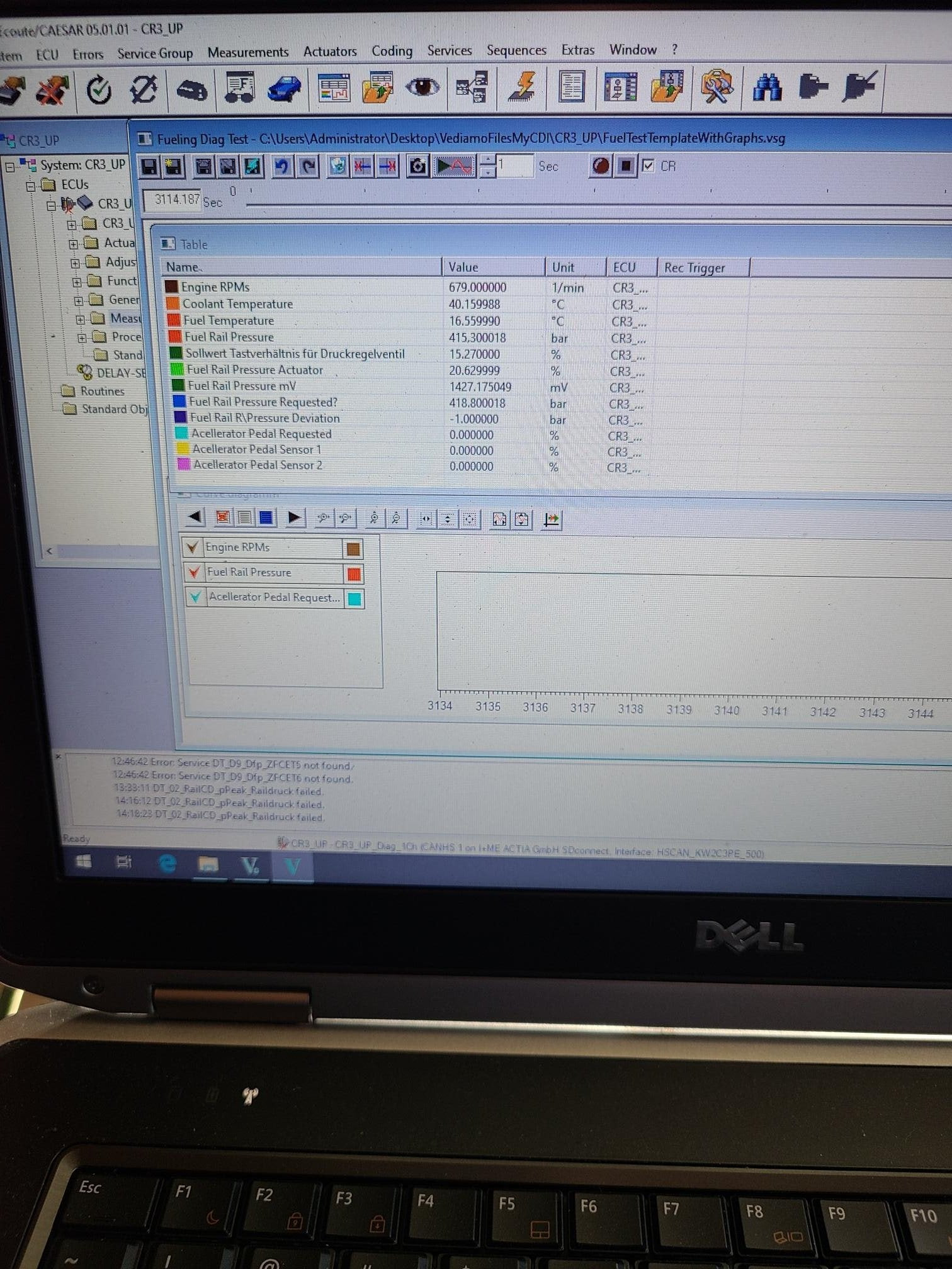
Xentry Diagnostic Tool Interface
3. Step-by-Step Guide to Viewing Live Data in Xentry
Once your system is set up, follow these steps to view live data in Xentry:
3.1. Step 1: Vehicle Selection
- Start Xentry: Open the Xentry Diagnostics software.
- Automatic Identification: Allow Xentry to automatically identify the vehicle by reading the VIN (Vehicle Identification Number).
- Manual Selection: If automatic identification fails, manually enter the VIN or select the vehicle model from the list.
3.2. Step 2: Accessing Control Units
- Quick Test: Perform a Quick Test to scan all available control units.
- Select Control Unit: Choose the specific control unit you want to monitor (e.g., Engine Control Unit (ECU), Transmission Control Unit (TCU)).
3.3. Step 3: Navigating to Live Data
- Actual Values: Look for options like “Actual Values,” “Live Data,” or “Measured Values.”
- Data Streams: Select the specific data streams you want to view (e.g., engine speed, coolant temperature, fuel pressure).
3.4. Step 4: Monitoring and Interpreting Data
- Real-time Display: Observe the data streams in real-time as the vehicle operates.
- Graphing: Use the graphing function to visualize data changes over time.
- Recording: Record data for later analysis.
For instance, if you’re diagnosing a misfire, monitor the individual cylinder misfire counts to identify which cylinder is causing the issue.
4. Common Data Parameters to Monitor
Knowing which parameters to monitor is crucial for effective diagnostics. Here are some common and important data parameters:
4.1. Engine Control Unit (ECU)
| Parameter | Description | Importance |
|---|---|---|
| Engine Speed (RPM) | Revolutions per minute of the engine | Basic indicator of engine operation |
| Coolant Temperature | Temperature of the engine coolant | Affects fuel mixture and engine performance |
| Intake Air Temperature | Temperature of the air entering the engine | Influences air density and fuel mixture |
| Mass Air Flow (MAF) | Amount of air entering the engine | Critical for calculating fuel delivery |
| Fuel Trim (Short/Long Term) | Adjustments made to the fuel mixture by the ECU | Indicates fuel system issues (e.g., leaks, sensor problems) |
| Oxygen Sensor Readings | Voltage output of the oxygen sensors | Monitors exhaust gas composition and catalytic converter efficiency |
| Throttle Position | Position of the throttle plate | Affects engine power and response |
| Ignition Timing | Timing of the spark ignition | Affects engine power and efficiency |
| Fuel Pressure | Pressure of the fuel in the fuel rail | Ensures proper fuel delivery to the injectors |
| Manifold Absolute Pressure | Pressure in the intake manifold | Used to calculate air density and fuel delivery |
4.2. Transmission Control Unit (TCU)
| Parameter | Description | Importance |
|---|---|---|
| Transmission Temp | Temperature of the transmission fluid | Prevents overheating and ensures proper lubrication |
| Gear Position | Current gear the transmission is in | Verifies correct gear selection |
| Input Speed | Speed of the transmission input shaft | Used to calculate torque converter slip and shift timing |
| Output Speed | Speed of the transmission output shaft | Indicates vehicle speed and transmission efficiency |
| Torque Converter Slip | Difference between input and output shaft speeds | Diagnoses torque converter issues |
| Solenoid Duty Cycles | Percentage of time the solenoids are active | Controls gear shifts and hydraulic pressure |
| Shift Times | Duration of gear shifts | Affects shift quality and transmission performance |
| Clutch Pressures | Hydraulic pressure applied to the clutches | Ensures smooth and precise gear engagement |
| Valve Body Pressures | Hydraulic pressure in the valve body | Controls fluid flow and overall transmission operation |
| Fluid Level | Transmission fluid level | Critical for proper transmission function and longevity |
4.3. Anti-Lock Braking System (ABS)
| Parameter | Description | Importance |
|---|---|---|
| Wheel Speed Sensors | Speed of each wheel | Detects wheel lock-up and controls ABS activation |
| Brake Pressure | Pressure in the brake lines | Monitors braking performance and detects leaks |
| ABS Activation | Status of the ABS system (active/inactive) | Verifies proper ABS function during braking |
| Lateral Acceleration | Force acting on the vehicle during turns | Used in stability control systems |
| Yaw Rate | Rate of rotation of the vehicle | Helps maintain vehicle stability |
| Steering Angle | Angle of the steering wheel | Used in conjunction with other sensors to control stability |
| Hydraulic Pump Motor | Status of the ABS hydraulic pump motor | Ensures proper hydraulic pressure for ABS function |
| Solenoid Valve Status | Status of the ABS solenoid valves | Controls brake pressure to individual wheels |
| Sensor Voltage Levels | Voltage levels of the ABS sensors | Verifies sensor integrity and detects wiring issues |
| Electronic Stability P | Status of the Electronic Stability Program (ESP) | Enhances vehicle stability and prevents skidding during adverse conditions |
4.4. Supplemental Restraint System (SRS)
| Parameter | Description | Importance |
|---|---|---|
| Airbag Deployment Status | Indicates whether airbags have been deployed | Verifies proper deployment and identifies system malfunctions |
| Seatbelt Buckle Status | Status of the seatbelt buckles | Ensures seatbelts are properly fastened during deployment |
| Occupancy Sensor | Detects the presence of a passenger | Adjusts airbag deployment based on occupancy |
| Impact Sensor Readings | Data from the impact sensors | Triggers airbag deployment during collisions |
| Rollover Sensor | Detects vehicle rollover | Activates rollover protection systems |
| Crash Data | Stored crash data from previous events | Helps diagnose issues related to airbag deployment |
| Warning Lamps | Status of the SRS warning lamps | Indicates system malfunctions and alerts the driver |
| Communication with ECU | Status of communication with the ECU | Ensures proper communication between the SRS and other vehicle systems |
| Voltage Levels of Components | Voltage levels of SRS components | Verifies component integrity and detects wiring issues |
| Diagnostic Trouble Codes | Diagnostic Trouble Codes (DTCs) related to SRS | Identifies specific issues within the SRS |
According to the National Highway Traffic Safety Administration (NHTSA), monitoring these parameters can significantly improve diagnostic accuracy and safety.
5. Interpreting Live Data: Tips and Tricks
Interpreting live data requires a combination of technical knowledge and practical experience. Here are some tips and tricks to help you:
5.1. Understanding Normal Ranges
- Reference Values: Consult the vehicle’s service manual for the normal operating ranges of each parameter.
- Comparative Analysis: Compare the current readings to the expected values.
- Deviation: Identify any deviations that could indicate a problem.
For instance, a coolant temperature reading above 220°F (104°C) could indicate an overheating issue.
5.2. Identifying Abnormal Patterns
- Fluctuations: Look for erratic fluctuations in data streams.
- Sticking Values: Identify parameters that are stuck at a certain value.
- Correlation: Analyze how different parameters correlate with each other.
For example, if the oxygen sensor readings are consistently low, it could indicate a rich fuel mixture.
5.3. Using Freeze Frame Data
- Capture Data: Use the freeze frame function to capture data when a fault code is triggered.
- Analyze Conditions: Analyze the conditions that led to the fault code.
- Pinpoint Issues: Use the freeze frame data to pinpoint the root cause of the problem.
5.4. Case Study: Diagnosing a Misfire
Consider a scenario where a Mercedes-Benz has a misfire. Here’s how live data can help:
- Connect Xentry: Connect Xentry and select the Engine Control Unit (ECU).
- Monitor Misfire Counts: View the misfire counts for each cylinder.
- Identify Cylinder: Identify the cylinder with the highest misfire count.
- Check Fuel Injector: Monitor the fuel injector pulse width for that cylinder.
- Compare Readings: Compare the reading with other cylinders.
- Analyze Data: If the pulse width is significantly different, the fuel injector could be faulty.
6. Advanced Techniques for Live Data Analysis
For complex diagnostic scenarios, advanced techniques can provide deeper insights.
6.1. Comparing Data Streams
- Multiple Parameters: Simultaneously monitor multiple parameters to identify correlations.
- Graphing Tools: Use graphing tools to visualize the relationships between data streams.
- Example: Compare engine speed and throttle position to diagnose throttle response issues.
6.2. Performing Actuator Tests
- Actuator Control: Use Xentry to activate or deactivate specific components.
- Verify Functionality: Verify the functionality of actuators by monitoring their response.
- Example: Activate the fuel pump relay to check fuel pressure.
6.3. Analyzing Sensor Data
- Sensor Readings: Monitor sensor readings to ensure they are within the specified range.
- Voltage and Resistance: Check the voltage and resistance of sensors to identify electrical issues.
- Example: Verify the voltage output of the MAF sensor.
6.4. Long-Term Monitoring
- Record Data: Record live data over an extended period to capture intermittent issues.
- Driving Conditions: Record data under different driving conditions (e.g., city, highway).
- Review Data: Review the recorded data to identify patterns and anomalies.
According to a study by the Society of Automotive Engineers (SAE), long-term monitoring can significantly improve the accuracy of diagnosing elusive problems.
7. Common Pitfalls and How to Avoid Them
Even with the right tools and techniques, certain pitfalls can hinder your ability to accurately interpret live data.
7.1. Ignoring Vehicle Specifications
- Reference Manuals: Always consult the vehicle’s service manual for accurate specifications.
- Incorrect Data: Avoid relying on generic data, which may not apply to the specific model.
- Impact: Misinterpretation and incorrect diagnoses.
7.2. Overlooking Basic Checks
- Visual Inspection: Perform a thorough visual inspection before diving into live data.
- Mechanical Issues: Identify obvious mechanical issues that could affect the data.
- Impact: Wasting time on electronic diagnostics when a simple mechanical fix is needed.
7.3. Misinterpreting Sensor Readings
- Sensor Operation: Understand how each sensor operates and what its normal readings should be.
- Diagnostic Codes: Relate sensor readings to diagnostic trouble codes (DTCs).
- Impact: Incorrectly diagnosing a sensor as faulty when the issue lies elsewhere.
7.4. Neglecting Wiring and Connections
- Electrical Issues: Check wiring and connections for corrosion, damage, or loose connections.
- Resistance Testing: Perform resistance tests to identify wiring problems.
- Impact: Overlooking simple wiring issues that can cause inaccurate sensor readings.
7.5. Over-Reliance on Data Alone
- Holistic Approach: Combine live data with other diagnostic methods, such as physical inspections and component testing.
- Context: Consider the vehicle’s history, symptoms, and driving conditions.
- Impact: Missing critical clues that could lead to a more accurate diagnosis.
8. The Future of Live Data Diagnostics
The field of automotive diagnostics is constantly evolving, with advancements in technology leading to more sophisticated live data analysis tools.
8.1. Enhanced Diagnostic Tools
- Advanced Sensors: Integration of more advanced sensors providing more detailed data.
- Wireless Communication: Wireless diagnostic interfaces for greater flexibility and convenience.
- Cloud Connectivity: Cloud-based diagnostic platforms for remote access and data sharing.
8.2. Artificial Intelligence (AI)
- Data Analysis: AI-powered diagnostic systems that can analyze live data in real-time.
- Pattern Recognition: AI algorithms that can identify subtle patterns and anomalies that humans might miss.
- Predictive Maintenance: AI-driven predictive maintenance systems that can anticipate potential issues before they occur.
8.3. Remote Diagnostics
- Remote Access: Ability to perform diagnostics remotely, reducing the need for physical presence.
- Expert Support: Access to remote experts who can assist with complex diagnostic scenarios.
- Telematics: Integration of telematics data for real-time monitoring and diagnostics.
According to a report by McKinsey & Company, the automotive diagnostics market is expected to grow significantly in the coming years, driven by advancements in technology and increasing demand for remote diagnostics.
9. Choosing the Right Diagnostic Tools from CARDIAGTECH.NET
Selecting the right diagnostic tools is essential for effective live data analysis. CARDIAGTECH.NET offers a wide range of high-quality diagnostic tools tailored to meet your specific needs.
9.1. Xentry Diagnostic Kits
- Comprehensive Kits: Complete diagnostic kits including the Xentry software, diagnostic interface, and necessary cables.
- Latest Updates: Regular software updates to ensure compatibility with the latest Mercedes-Benz models.
- Benefits: Accurate diagnostics, efficient repairs, and access to the latest vehicle information.
9.2. Diagnostic Interfaces
- Certified Interfaces: Mercedes-Benz certified diagnostic interfaces (e.g., Xentry Connect, C4/C5/C6 multiplexers).
- Reliable Performance: Reliable and stable performance for accurate data retrieval.
- Benefits: Seamless integration with Xentry software, robust connectivity, and dependable performance.
9.3. Software Subscriptions
- Flexible Options: Flexible subscription options to suit your budget and diagnostic needs.
- Access to Updates: Access to the latest software updates, vehicle data, and diagnostic procedures.
- Benefits: Continuous improvement in diagnostic capabilities, access to the latest vehicle information, and cost-effective solutions.
9.4. Accessories and Cables
- High-Quality Accessories: High-quality cables, adapters, and accessories for reliable connectivity.
- Durable Construction: Durable construction to withstand the rigors of daily use.
- Benefits: Reliable connections, accurate data transmission, and long-lasting performance.
9.5. Training and Support
- Comprehensive Training: Comprehensive training programs to help you master live data diagnostics.
- Expert Support: Access to expert technical support for assistance with diagnostic challenges.
- Benefits: Enhanced diagnostic skills, improved efficiency, and access to expert knowledge.
10. Frequently Asked Questions (FAQs)
1. What is Xentry and why is it used for Mercedes-Benz vehicles?
Xentry is the official diagnostic software for Mercedes-Benz vehicles, offering comprehensive diagnostics, ECU programming, and access to repair information, as confirmed by Daimler.
2. What are the key hardware and software requirements for viewing live data in Xentry?
The key requirements include Xentry software, a compatible diagnostic interface, a computer meeting Xentry’s system requirements, necessary cables, and a stable internet connection.
3. How do I access live data in Xentry after connecting to the vehicle?
After connecting to the vehicle, perform a Quick Test, select the desired control unit (e.g., ECU), and navigate to options like “Actual Values” or “Live Data.”
4. What common data parameters should I monitor in the Engine Control Unit (ECU)?
Common parameters include engine speed (RPM), coolant temperature, intake air temperature, mass air flow (MAF), fuel trim, oxygen sensor readings, throttle position, and fuel pressure.
5. What should I monitor in the Transmission Control Unit (TCU)?
Key parameters to monitor in the TCU include transmission temperature, gear position, input speed, output speed, torque converter slip, solenoid duty cycles, and shift times.
6. How can I interpret live data effectively?
Understand normal ranges by consulting the vehicle’s service manual, identify abnormal patterns like erratic fluctuations, and use freeze-frame data to analyze conditions that trigger fault codes.
7. What are some common pitfalls to avoid when interpreting live data?
Avoid ignoring vehicle specifications, overlooking basic checks, misinterpreting sensor readings, neglecting wiring and connections, and over-relying on data alone.
8. How can advanced techniques enhance live data analysis?
Advanced techniques include comparing data streams, performing actuator tests, analyzing sensor data (voltage, resistance), and conducting long-term monitoring under various driving conditions.
9. What future advancements are expected in live data diagnostics?
Future advancements include enhanced diagnostic tools with advanced sensors, AI-powered diagnostic systems for real-time data analysis, and remote diagnostics for reducing physical presence and accessing expert support.
10. Why should I choose diagnostic tools from CARDIAGTECH.NET?
CARDIAGTECH.NET offers comprehensive Xentry diagnostic kits, certified diagnostic interfaces, flexible software subscriptions, high-quality accessories, and training/support to enhance diagnostic skills and improve efficiency.
Mastering how to view live data in Xentry is crucial for efficient and accurate automotive diagnostics. With the right tools and knowledge, you can quickly identify and resolve complex issues, ensuring customer satisfaction and enhancing your reputation.
Ready to elevate your diagnostic capabilities? Contact CARDIAGTECH.NET today at 276 Reock St, City of Orange, NJ 07050, United States, or via WhatsApp at +1 (641) 206-8880. Visit our website CARDIAGTECH.NET and let us help you find the perfect diagnostic tools to meet your needs. Don’t miss out on the opportunity to transform your repair process with CARDIAGTECH.NET’s advanced solutions. Get in touch now and experience the difference.
